
Introduction
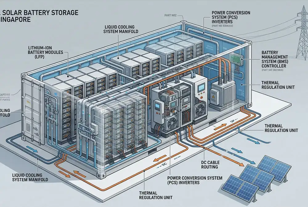
Investing in commercial solar battery storage integrates utility-scale solar photovoltaics (PV), advanced electrochemical battery racks, bidirectional power conversion systems (PCS), multi-tiered battery management systems (BMS), and algorithmic energy management systems (EMS). This combined infrastructure captures non-dispatchable surplus solar generation during low-marginal-value periods and strategically dispatches it during peak grid pricing windows or critical outage events. For industrial manufacturing facilities, cold storage warehouses, and large commercial real estate assets, rapidly inflating utility peak demand tariffs and severe export curtailment make pure grid-export solar models financially non-viable.
According to global Battery Energy Storage System (BESS) deployment analytics published by BloombergNEF in their Energy Storage Outlook, global commercial battery storage capacity is accelerating at a compound annual growth rate (CAGR) exceeding 34%. Behind-the-meter (BTM) storage is rapidly transitioning from a passive sustainability credential into an indispensable, revenue-generating, and risk-mitigating operational operational imperative.
1. System Architecture At-a-Glance
A fully integrated Commercial & Industrial (C&I) solar-plus-storage installation relies on six core functional sub-systems. Each subsystem plays a distinct role in balancing power quality, electrochemical safety, and financial dispatch optimization.
| System Parameter | Technical & Operational Definition | Buyer Benefit / High-Value ROI Impact |
|---|---|---|
| Solar PV Array | High-efficiency Tier-1 monocrystalline module string array generating direct current (DC) electricity via the photoelectric effect during peak solar irradiance. | Locks in zero-marginal-cost clean energy; directly offsets retail volumetric utility energy charges ($/kWh) during daylight operating shifts. |
| Battery Storage System | Industrial-grade Lithium Iron Phosphate (LiFePO4 / LFP) electrochemical cell enclosures configured into high-voltage DC rack assemblies. | Eliminates low-value grid feed-in penalties; stores low-cost energy for automatic discharge during premium peak tariff windows or emergency grid outages. |
| Power Conversion System (PCS) | Four-quadrant bidirectional power inverter using high-frequency IGBT/SiC semiconductors to convert power between DC (battery/PV) and 3-phase AC grid lines. | Ensures seamless, distortion-free power delivery (< 3% THD) to heavy inductive motors and sensitive automated production equipment; provides rapid VAR reactive power compensation. |
| Battery Management System (BMS) | 3-tier embedded architecture monitoring cell-level voltage, current, temperature, State of Charge (SOC), and State of Health (SOH) with active cell balancing. | Extends system operating lifecycle beyond 6,000–8,000 cycles (15+ years); provides fail-safe, multi-layer protection against thermal runaway events. |
| Energy Management System (EMS) | Edge computing hardware and cloud AI algorithms executing real-time tariff tracking, load forecasting, dynamic peak shaving, and economic dispatch optimization. | Automates multi-stream financial arbitrage; maximizes monthly peak demand charge reductions without requiring manual plant operator intervention. |
| Utility Grid Point of Interconnection | High-voltage main distribution board (MDB) interface featuring motorized isolation breakers, protection relays, and bidirectional revenue metering. | Functions as an ultimate energy backup; enables participation in utility Demand Response (DR) programs and Virtual Power Plants (VPP). |
2. Fundamentals of Commercial Solar Battery Storage Systems
Defining Heavy-Duty Industrial Energy Storage Architecture
Plant engineers and facility directors must recognize that a true commercial and industrial (C&I) solar battery storage system is fundamentally distinct from scaled-up residential energy storage. A C&I system represents a heavy-duty, utility-grade power infrastructure designed to integrate directly with medium-voltage (MV) or low-voltage (LV) industrial distribution networks. These systems accommodate massive step-load transitions, continuous three-phase imbalance, dynamic motor starting inrush currents, and rigorous 24/7 operating cycles under demanding environmental conditions.
The Synergy Between Solar PV and Electrochemical Storage
Solar photovoltaic arrays generate power according to a bell-shaped solar irradiance curve, peaking precisely between 11:00 AM and 2:00 PM. Conversely, industrial load profiles rarely align with this curve; manufacturing plants often experience heavy morning startup spikes (7:00 AM – 10:00 AM) or maintain flat continuous 24-hour demand baselines. Integrating BESS converts non-dispatchable variable solar generation into a controllable, dispatchable asset. The battery acts as a dynamic energy buffer, absorbing excess generation during midday irradiance peaks and discharging it during high-cost utility tariff windows or heavy facility load events.
Technical Comparison: Commercial vs. Residential Battery Storage
- Voltage & Phase Architecture: Residential systems typically operate on single-phase or split-phase 48V DC or 400V DC buses. C&I BESS operates on high-voltage DC buses ranging from 750V DC to 1500V DC, interfacing directly with 3-phase 400V, 480V, or step-up 10kV/35kV utility networks.
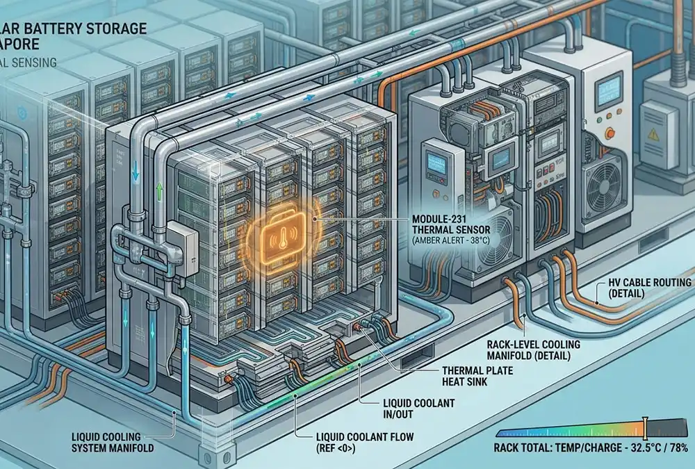
- Thermal Management Technology: Residential units rely on passive convection or basic air-cooling. Industrial BESS utilizes liquid-cooling loops with precision glycol chillers, maintaining cell-to-cell thermal variance below 2.0°C to prevent localized accelerated degradation and thermal runaway risks.
- Inrush & Fault Capacity: Commercial PCS units offer up to 150% overload capability for 10–30 seconds to support severe inductive motor startup surges, whereas residential inverters trip under high localized surge demands.
- Control Logic & Communications: C&I systems employ Modbus TCP, CANopen, and IEC 61850 industrial protocols integrated with SCADA, PLC, and machine-learning EMS platforms for sub-second demand response, contrasting with simple mobile app controls in residential units.
3. Operational Mechanics & Daily Operating Cycles
The daily operational lifecycle of a grid-tied commercial solar-plus-storage system is governed by four automated operational phases executing seamless transitions based on real-time power metering, state of charge (SOC), and time-of-use (TOU) tariff schedules.
Phase 1: Daytime Solar Generation & Automated BESS Charging (09:00 – 14:00)
Solar PV generation exceeds immediate facility baseline consumption. High-efficiency PCS channels excess power directly into charging the LFP battery racks at controlled C-rates (typically 0.5C to 0.8C). On-site solar self-consumption efficiency is elevated from an unbuffered 35–40% up to 90–95%, preventing uncompensated surplus export to the utility grid.
Phase 2: On-Peak Demand Shaving & Load Injection (14:00 – 20:00)
As utility peak pricing windows open and facility power consumption accelerates, the EMS triggers high-rate discharging. The BESS injects power into the main distribution switchboard, capping total grid import at a pre-programmed kilowatt threshold. This eliminates costly 15-minute peak demand spikes and high-tier volumetric electricity fees.
Phase 3: Post-Solar Off-Peak Load Offset & Arbitrage (20:00 – 23:00)
In the absence of solar radiation, the remaining usable SOC within the battery storage system continues supplying evening baseline operations (HVAC, lighting, automated logistics systems), avoiding expensive shoulder or evening peak utility rates.
Phase 4: Emergency Islanding Mode & Microgrid Backup Operations (Grid Outage Event)
Upon detecting utility grid voltage loss or frequency destabilization, the system’s automated transfer switch (ATS) opens within 10–20 milliseconds. The PCS transitions from grid-following to grid-forming mode, creating a localized microgrid island. Critical plant equipment, cold storage compressors, and IT data centers remain continuously energized without operational interruption.
4. Exhaustive Hardware Component Architecture
A turnkey industrial BESS integrates multiple hardware layers engineered for extreme reliability, safety compliance, and power conversion efficiency.
- Tier-1 Monocrystalline Solar PV Modules: Built with N-type TOPCon or HJT cell technology offering module efficiencies >22.5%, low temperature coefficients (-0.30%/°C), and minimal linear power degradation (<0.4% annually over 30 years).
- Lithium Iron Phosphate (LiFePO4) Battery Racks: Premium prismatic LFP cells engineered for intrinsic thermal stability (thermal runaway threshold >270°C). Arranged in series-parallel configurations to form high-density DC racks equipped with cell balance modules and integrated temperature sensors.
- Three-Tier Battery Management System (BMS): Comprising Cell Monitoring Units (BMU), Rack Master Controllers (RBMS), and System Master Controllers (SBMS). Executes real-time voltage/current sampling, SOC/SOH estimation using extended Kalman filtering, and multi-stage over-current, over-voltage, and over-temperature protection trip triggers.
- Bidirectional Power Conversion System (PCS): Industrial four-quadrant inverter featuring carrier phase-shifted PWM technology, active damping control, and < 3% Total Harmonic Distortion (THD). Capable of reactive power injection (PF adjustable from 0.8 leading to 0.8 lagging) for power factor correction.
- Edge Energy Management System (EMS) & Cloud IoT Platform: High-reliability industrial PC executing real-time dispatch algorithms locally while transmitting telemetry via MQTT/TLS to cloud platforms for predictive maintenance, lifecycle modeling, and multi-site aggregator controls.
- Electrical Isolation, Switchgear & Step-Up Transformers: Air-insulated or vacuum switchgear equipped with motorized breakers, surge protection devices (SPD), and dry-type isolation transformers stepping voltage up to matching facility distribution levels (e.g., 480V to 11kV/33kV).
- Liquid Thermal Management & Fire Suppression (NFPA 855 Compliant): Closed-loop liquid cooling piping delivering uniform temperature control across all cells. Safety suite integrates off-gas detection (detecting early hydrogen/CO venting), aerosol or clean-agent fire suppression, deflagration venting panels, and dedicated water deluge connections adhering strictly to NFPA 855 standards.
| Hardware Component | Primary Function | Engineering Verification Checklist | Direct Operational Benefit |
|---|---|---|---|
| PV Array | Solar Energy Capture | kWp rating, N-type cell degradation, bifacial gain factor | Provides zero-carbon, low-cost baseline power |
| LFP Battery Racks | Electrochemical Energy Storage | Usable kWh capacity, DoD rating (90%+), cycle life (>6000 cycles) | High energy density, minimal degradation, non-combustible stability |
| 3-Tier BMS | Safety Telemetry & Balancing | SOC accuracy (<2%), cell temperature sampling rate (<100ms) | Prevents cell imbalance, maximizes usable pack capacity |
| PCS Inverter | DC/AC Bidirectional Conversion | Peak efficiency (>98.5%), switching time (<10ms for islanding) | High conversion efficiency minimizes round-trip energy losses |
| EMS Controller | Algorithmic System Control | Local response speed, forecasting accuracy, API flexibility | Extracts maximum financial savings from complex multi-rate tariffs |
| Thermal & Fire Safety | Hazard Mitigation & Cooling | UL 9540A burn test report, NFPA 855 compliance, liquid chiller COP | Ensures rapid local fire marshal approvals and uninterrupted asset safety |
5. Strategic Value Drivers: Economic vs. Operational Categorization
Adding battery storage to a commercial solar installation produces dual streams of value. Commercial buyers must evaluate both hard financial returns (Economic Drivers) and operational security benefits (Operational Drivers).
Economic Value Drivers (Direct Cash Flow Impact)
- Peak Demand Charge Reduction ($/kW-month): Shaving high 15-minute average demand spikes that account for 30%–50% of total commercial utility bills.
- Time-of-Use (TOU) Energy Arbitrage ($/kWh spread): Storing zero-cost solar or cheap off-peak grid power and discharging during multi-fold peak tariff rates.
- Elimination of Grid Feed-In Penalties & Export Curtailment: Capturing generated solar power that would otherwise be curtailed or exported for negligible feed-in tariffs (FiT).
- Participation in Ancillary Services & VPP Networks: Earning passive revenue from utility grid operators by providing frequency response (FFR), spinning reserves, and capacity market support.
Operational & Risk Mitigation Value Drivers
- Microgrid Islanding & Power Resilience: Safeguarding critical manufacturing lines, cold storage inventory, and process automation against power outages.
- Point-of-Interconnection Power Quality Optimization: Active harmonic filtering, dynamic power factor correction, and real-time phase balancing to protect expensive site equipment.
- Grid Capacity Constraint Deferral: Bypassing utility transformer upgrade delays by utilizing BESS to cap maximum site demand within existing grid limits.
- Fleet Electrification & High-Speed EV Charging Support: Buffering high-power DC fast-charger spikes to prevent massive site demand penalties.
6. Economic Comparison: Storing Energy vs. Grid Export
Historical net metering policies (1:1 retail credit) are being systematically dismantled across major markets globally (e.g., California NEM 3.0, European feed-in tariff restructuring). The financial equation has fundamentally shifted in favor of high self-consumption.
The Math of Modern Solar Economics: When utility import tariffs sit at $0.32/kWh and grid export buyback rates are slashed to $0.05/kWh, exporting solar power results in an immediate loss of $0.27/kWh in potential economic value. Retaining that electron on-site via an LFP battery captures the full retail offset value ($0.32/kWh minus round-trip efficiency losses).
Furthermore, utility-imposed zero-export constraints in congested distribution grids automatically shut down solar inverters during irradiance peaks unless a BESS is present to absorb surplus generation, leading to total waste of clean energy assets.
7. C&I Solar + BESS Sizing Framework & Mathematical Methodology
Sizing a commercial storage system based solely on rooftop square footage or total annual kWh consumption is a critical engineering mistake. Precise sizing requires 15-minute interval load analysis (Green Button data) mapped against high-resolution solar irradiance profiles.
The 6-Step C&I Sizing Methodology™
Step 1: Calculate Daily Solar Surplus (kWh)
Excess Solar (kWh) = Total Daily PV Generation (kWh) – Direct Daytime Site Consumption (kWh)
Step 2: Determine Target Peak Shaving Power (kW)
Target BESS Power (kW) = Observed Peak Demand Spike (kW) – Target Grid Import Ceiling (kW)
Step 3: Calculate Required Usable Energy Capacity (kWh)
Usable Energy (kWh) = Target Shaved Power (kW) × Peak Window Duration (Hours)
Step 4: Factor in Round-Trip Efficiency (RTE) & Usable Depth of Discharge (DoD)
Nameplate Capacity (kWh) = Usable Energy (kWh) / [ RTE (%) × Usable SOC Operating Window (%) ]
(Example: Assuming 88% RTE and 90% usable SOC window: Nameplate = Usable / (0.88 × 0.90))
Step 5: Account for End-of-Life (EOL) Degradation Margin
Year-1 Installed Capacity (kWh) = Required Nameplate Capacity (kWh) / EOL Retention Factor (e.g., 0.80 for 80% EOL)
Step 6: Validate via 15-Minute Interval Data Simulation
Run algorithmic multi-year simulation across 35,040 annual interval data points to confirm zero unhandled demand spikes and verify financial NPV maximization.
8. Standard Industrial BESS Product Configurations
To simplify engineering, procurement, and construction (EPC) processes, we provide four standardized, pre-engineered liquid-cooled outdoor BESS configurations:
| BESS Model | Target Application / Facility Type | Technical Specifications | Key Selling Point / Buyer Advantage |
|---|---|---|---|
| 100 kWh Cabinet BESS | Small commercial buildings, EV charging hubs, workshops, gas stations | 50kW / 100kWh, All-in-One IP55 outdoor cabinet, integrated PCS & BMS | Ultra-compact footprint (<1.5m²), minimal site civil work, plug-and-play installation |
| 261 kWh Outdoor BESS | Medium manufacturing plants, cold storage warehouses, commercial plazas | 100kW / 261kWh, Smart Liquid Cooling loop, cell temp delta < 2.0°C | Optimal energy density balance, extended cycle life (>8000 cycles at 25°C), high ROI |
| 418 kWh Modular BESS | Heavy industrial facilities, multi-MW solar expansion projects, data centers | 200kW / 418kWh, Modular rack architecture, high-power DC bus interface | Seamless parallel scalability up to 5MW / 10MWh, individual rack maintenance isolation |
| 1 MWh Containerized BESS | Large industrial parks, utility grid tie-ins, large-scale microgrids | 500kW / 1000kWh, Turnkey 20ft ISO container, integrated HVAC, aerosol & fire suppression | Complete grid-level power delivery, extreme ruggedized weatherproofing, full SCADA integration |
9. Software Intelligence: How EMS Maximizes BESS Economic Value
Hardware accounts for system capacity, but software dictates financial performance. According to operational engineering reports published by the National Renewable Energy Laboratory (NREL), dynamic software-driven control algorithms increase commercial battery revenue streams by up to 28% compared to basic static timer schedules.
- Predictive Load & Solar Forecasting: Neural network models analyze historical consumption trends, ambient temperature forecasts, and cloud cover imagery to predict next-day facility demand peaks and solar output.
- Dynamic Peak Shaving Thresholds: Rather than discharging at a fixed kilowatt trigger, the EMS continuously adjusts its peak shaving target throughout the month based on real-time building load dynamics to prevent early depletion of energy reserves.
- Multi-Objective Co-Optimization: The software balances competing priorities—such as minimizing demand charges, maximizing TOU arbitrage, limiting battery degradation, and preserving emergency backup reserve levels—in real time.
10. Comprehensive Cost Structures, Financial Metrics & ROI Calculation
Full Turnkey CAPEX Breakdown (Why $/kWh Bare-Rack Quotes Are Misleading)
A common procurement mistake is evaluating C&I BESS feasibility based solely on unintegrated battery rack prices (e.g., $130–$180/kWh). Fully installed, turnkey C&I project CAPEX typically ranges between $400 and $650 per usable kWh.
Turnkey Capital Expenditure (CAPEX) Composition:
- Equipment Costs (50% – 60%): LFP battery racks, bidirectional PCS, 3-tier BMS, liquid cooling system, fire protection, and EMS gateway hardware.
- Balance of System (BOS) & Electrical (15% – 20%): Isolation transformers, MV switchgear, high-voltage cabling, containment, and protection relays.
- Civil & Structural Engineering (10% – 15%): Concrete pad construction, environmental containment bunding, security fencing, and trenching.
- Soft Costs, Permitting & Interconnection (10% – 15%): Utility interconnection impact studies, AHJ fire marshal approvals, UL 9540 field certifications, engineering labor, and commissioning.
Mathematical Models for Financial Evaluation
1. Simple Payback Period Formula:
Simple Payback (Years) = Net Installed Turnkey CAPEX ($) / Annual Net Cash Savings ($/Year)
2. 15-Year Life Cycle Net Present Value (NPV):
NPV = ∑ [ (Annual Savings_t – OPEX_t) / (1 + r)^t ] – Initial CAPEX
Where t = Year (1 to 15), OPEX = Operation & Maintenance costs (including cell capacity augmentation), and r = Corporate Discount Rate (e.g., 8%).
Why Bankable Modeling Requires IRR and Sensitivity Analysis: Simple payback metrics fail to account for utility tariff inflation (typically 3%–6% annually), electrochemical capacity degradation curves, system augmentation costs at Year 8–10, and tax incentives (e.g., Investment Tax Credits / Accelerated Depreciation). Sophisticated C&I investors require multi-scenario Internal Rate of Return (IRR) sensitivity models testing best-case, base-case, and worst-case electricity rate escalation scenarios.
11. Post-Installation Risks, Field Pitfalls & Engineering Solutions
Feedback from industrial plant managers, EPC engineers, and field technicians across renewable energy forums (such as Reddit’s r/renewableenergy and r/solar) highlights recurring post-commissioning operational challenges. Below is an engineering analysis of these failure modes and their mitigation protocols:
| Observed Operational Failure Mode | Root Cause Technical Analysis | Engineering Mitigation Protocol |
|---|---|---|
| BMS-PCS Communication Drops | EMC interference or unshielded Modbus RS485/CANbus wiring causing packet loss and spurious inverter fault trips. | Deploy industrial-grade fiber-optic communications or double-shielded twisted pair cabling with hardware watchdog auto-reconnects. |
| EMS Peak Shaving Misses | Rigid control thresholds failing during unpredicted facility step-loads or sudden solar cloud passage. | Implement sub-second dynamic predictive EMS dispatch algorithms with real-time solar irradiance sensors. |
| State-of-Charge (SOC) Drift | Accumulation of current integration errors (Coulomb counting) during continuous partial state-of-charge (pSOC) cycling. | Execute automated full recalibration cycles (100% SOC top-balancing) via EMS software scheduling during off-peak periods. |
| Liquid Cooling System Maintenance Faults | Coolant pressure degradation, radiator clogging, or air pockets causing cell thermal throttling under summer heat. | Mandate annual coolant sampling, automated pressure sensing, and dual-redundant circulation pumps. |
| Permitting & AHJ Delays | Non-compliance with local fire codes, lacking UL 9540A explosion mitigation reports, or improper setback distances. | Engage local fire marshals (AHJ) during preliminary design; utilize fully certified UL 9540 standard enclosures. |
12. Architectural Selection: Modular vs. All-in-One Integrated Cabinet
Selecting between modular rack architecture and turnkey all-in-one cabinet systems depends on site physical space constraints, future load expansion plans, and maintenance capabilities.
| Evaluation Feature | Modular BESS Architecture | All-in-One Integrated Cabinet | Strategic Buyer Advantage |
|---|---|---|---|
| Scalability & Expansion | Incremental rack additions to existing DC bus | Fixed storage capacity per block; parallel full cabinets | Modular allows lower initial CAPEX with phased expansion as factory loads grow. |
| Maintenance & Serviceability | Hot-swappable module replacement at rack level | Requires manufacturer field engineering intervention | Modular architecture minimizes system downtime during component repairs. |
| Installation Velocity | Requires extensive field DC interconnect cabling | Factory pre-wired; simple AC grid drop connection | All-in-One cuts site commissioning labor costs by up to 60%. |
13. Grid Interconnection Standards & Electrical Interfacing
Behind-the-meter (BTM) commercial storage systems connect directly to the facility’s main low-voltage or medium-voltage distribution panel. Interconnection compliance requires strict adherence to international grid safety codes:
- IEEE 1547-2018 / UL 1741 SB Standard: Mandates smart inverter capabilities including anti-islanding protection, active voltage regulation (Volt-VAR), frequency-watt response, and low/high voltage ride-through (LHVRT) performance.
- UL 9540 & UL 9540A Certification: System-level fire safety standards. UL 9540A evaluates thermal runaway fire propagation at the cell, module, and rack levels to prove fire will not spread beyond a single cabinet.
- NFPA 855 Installation Mandates: Governs physical spatial separation (minimum 3 ft / 0.9 m spacing from structures), maximum allowable energy capacities per fire control area, and mandatory off-gas detection linked to automatic ventilation.
14. Procurement Guidance: Choosing Manufacturers and EPC Contractors
BESS Manufacturer Selection Criteria
- In-house cell sorting, ultrasonic welding, and automated pack assembly capabilities.
- Fully integrated supply chain control across BMS, PCS, and thermal management hardware.
- Globally verified third-party bankability and track record (>1 GWh cumulative operating deployments).
- Guaranteed cell performance degradation curves backed by tier-1 re-insurance policies.
EPC Installer Selection Criteria
- Demonstrated experience securing utility high-voltage interconnection approvals in the local utility jurisdiction.
- In-house civil, structural, and high-voltage electrical engineering teams.
- Proven compliance handling NFPA 855 and local fire marshal (AHJ) permitting workflows.
- Established 24/7 localized O&M response capabilities with local spare parts warehousing.
15. Engineering Advantage: Why AnengJi for Commercial Solar Storage
AnengJi delivers fully integrated C&I energy storage solutions engineered for maximum financial return, bankability, and decade-plus operational longevity:
- Vertical Integration Efficiency: Factory-level pre-integration of LFP chemistry, BMS logic, bidirectional PCS hardware, and liquid cooling systems eliminates site integration friction and software incompatibilities.
- Interval-Data Precision Sizing: Our engineering team utilizes proprietary simulation tools modeling 15-minute interval load data to eliminate costly equipment oversizing and maximize net project IRR.
- Industrial-Grade Thermal Performance: Advanced liquid cooling technology maintains cell temperature variance below 2.0°C, extending lifecycle duration and ensuring safe performance under high ambient temperatures up to 55°C.
- Lifetime Asset Assurance: End-to-end support spanning initial feasibility modeling, local fire marshal permitting support, system commissioning, and long-term remote O&M monitoring.
16. Commercial Solar + BESS Project Execution Checklist
1. Site & Electrical Infrastructure Assessment
Verify main service panel rating (Amps), transformer headroom, short-circuit current availability, outdoor concrete pad space, and required fire setbacks.
2. Load Profile & Solar Generation Mapping
Acquire 12–24 months of 15-minute interval utility load data (Green Button CSV), measure maximum demand spikes, and model rooftop PV generation profiles.
3. Safety, Codes & Interconnection Compliance
Confirm UL 9540/9540A certifications, NFPA 855 fire separation clearance, initiate early local AHJ fire marshal consultation, and submit utility interconnection requests.
4. Financial Pro-Forma & ROI Modeling
Build 15-year cash flow models including demand charge structures, TOU rate spreads, degradation augmentation schedules, tax incentives, NPV, and IRR sensitivity.
Request a Commercial Solar + BESS Assessment
Ready to eliminate heavy utility demand charges and secure long-term operational power resilience? Submit your site load data to receive a complimentary custom BESS sizing analysis and financial IRR projection from our engineering team.
Need a quick technical reference first? Download the C&I Solar + Storage Engineering Checklist.
 https://anengjipower.com/wp-content/uploads/2026/06/epc-vs-turnkey-solar-project-bess.webp
675
1000
Charging Station Engineer
https://anengjipower.com/wp-content/uploads/2025/09/anengji-dc-fast-charging-station-manufacturer-and-supplier-logo-white-1.png
Charging Station Engineer2026-06-22 07:16:042026-06-24 07:13:17What Is the Difference Between EPC and Turnkey Contract Models in Energy Projects?
https://anengjipower.com/wp-content/uploads/2026/06/epc-vs-turnkey-solar-project-bess.webp
675
1000
Charging Station Engineer
https://anengjipower.com/wp-content/uploads/2025/09/anengji-dc-fast-charging-station-manufacturer-and-supplier-logo-white-1.png
Charging Station Engineer2026-06-22 07:16:042026-06-24 07:13:17What Is the Difference Between EPC and Turnkey Contract Models in Energy Projects? https://anengjipower.com/wp-content/uploads/2026/06/anengji-commercial-solar-plus-storage-benefits-site.webp
675
1000
Charging Station Engineer
https://anengjipower.com/wp-content/uploads/2025/09/anengji-dc-fast-charging-station-manufacturer-and-supplier-logo-white-1.png
Charging Station Engineer2026-06-20 14:34:102026-06-20 14:37:43What Are the Top Benefits of Solar Battery Storage in Factories?
https://anengjipower.com/wp-content/uploads/2026/06/anengji-commercial-solar-plus-storage-benefits-site.webp
675
1000
Charging Station Engineer
https://anengjipower.com/wp-content/uploads/2025/09/anengji-dc-fast-charging-station-manufacturer-and-supplier-logo-white-1.png
Charging Station Engineer2026-06-20 14:34:102026-06-20 14:37:43What Are the Top Benefits of Solar Battery Storage in Factories?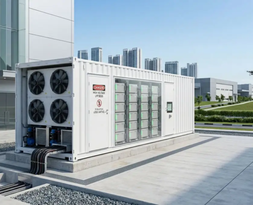 https://anengjipower.com/wp-content/uploads/2026/06/modular-commercial-solar-battery-storage-cabinet.webp
675
1000
Charging Station Engineer
https://anengjipower.com/wp-content/uploads/2025/09/anengji-dc-fast-charging-station-manufacturer-and-supplier-logo-white-1.png
Charging Station Engineer2026-06-18 09:16:522026-07-03 03:05:13What Is Solar Battery Storage? Complete C&I Engineering Guide
https://anengjipower.com/wp-content/uploads/2026/06/modular-commercial-solar-battery-storage-cabinet.webp
675
1000
Charging Station Engineer
https://anengjipower.com/wp-content/uploads/2025/09/anengji-dc-fast-charging-station-manufacturer-and-supplier-logo-white-1.png
Charging Station Engineer2026-06-18 09:16:522026-07-03 03:05:13What Is Solar Battery Storage? Complete C&I Engineering Guide


Leave a Reply
Want to join the discussion?Feel free to contribute!