
Introduction
Direct Technical Answer
A BESS does not connect to the grid directly through the battery. The typical path is Battery → BMS → PCS → Switchgear → Transformer → Metering/PCC/POI → Grid, with protection relays, EMS/SCADA software, and utility interconnection requirements governing the active power flow at the coupling point. Executing a successful BESS Grid Connection requires aligning the electrochemical DC profile with medium-voltage grid dynamics while complying with strict IEEE 1547, IEC 62933, and local utility codes.
BESS Grid Connection at a Glance
| Parameter | What It Determines | Engineering & Buyer Value |
|---|---|---|
| BESS Power | Maximum continuous PCS output capability (kW/MW) | Defines peak shaving depth and instant demand response capability. |
| BESS Energy | Total usable storage capacity over time (kWh/MWh) | Determines maximum discharge duration during peak utility tariff hours. |
| POI / PCC | Physical and legal boundary where asset joins grid | Sets ownership demarcation, protection testing zones, and billing meters. |
| Grid Voltage | Site connection level (LV: 400V/480V or MV: 11kV-34.5kV) | Dictates switchgear rating, cable sizing, and transformer selection costs. |
| Import Limit | Maximum power the facility is permitted to pull from utility | Prevents tripping utility feeders during fast battery charging sequences. |
| Export Limit | Maximum reverse power flow permitted into utility grid | Avoids costly grid upgrades by implementing active EMS power capping. |
| PCS Architecture | Bidirectional DC to AC power conversion topology | Governs total round-trip efficiency, harmonic distortion, and reactive power. |
| Protection System | Safety relays (59, 27, 81O/U, 78) and motorized breakers | Isolates fault currents in milliseconds, protecting facility and utility assets. |
| EMS / SCADA | Intelligent orchestration, dispatch algorithms, utility protocol | Unlocks automated revenue generation, demand shaving, and remote monitoring. |
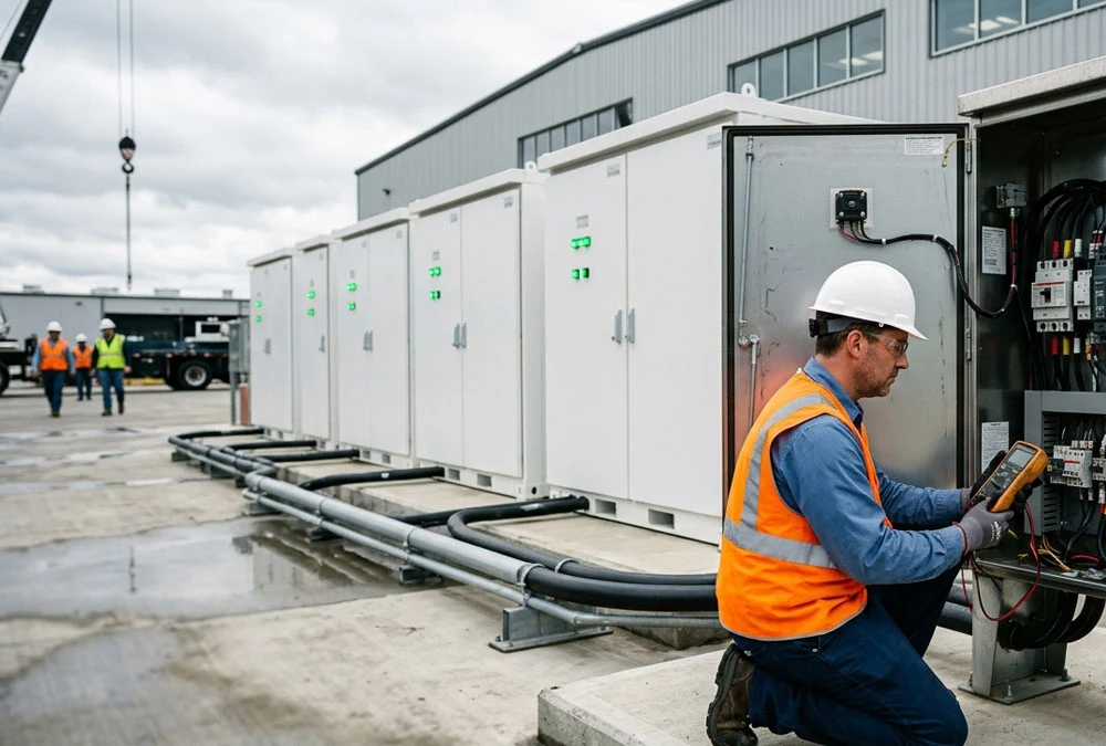
Navigating commercial and industrial (C&I) energy infrastructure demands absolute clarity regarding how a battery energy storage grid connection physically and digitally integrates with facility switchgear. As industrial plants add massive loads like DC fast chargers or high-power robotics, the regional utility grid faces mounting stress. According to the IEA Grid & Energy Storage Market Analysis, over 1,500 GW of renewable energy and energy storage projects worldwide are currently delayed in interconnection queues—largely due to technical compliance bottlenecks at the point of common coupling. Simply purchasing battery racks won’t solve facility power constraints. You must integrate a robust, code-compliant BESS grid connection framework that handles transient voltage sags, short-circuit currents, and strict grid operator export limits. This comprehensive engineering guide breaks down the physical power chain, protection requirements, utility interconnection studies, and control setups needed to deliver a bankable commercial BESS grid connection.
How Does a BESS Connect to the Grid?
Connecting energy storage to a commercial building or industrial park is not like plugging in a heavy-duty industrial motor. Electrochemical cells store direct current (DC), whereas the utility grid and your plant distribution panel operate entirely on alternating current (AC). A reliable system relies on precise power conversion, isolation switchgear, protection relays, and active controller dispatching.
The Basic Grid-Connected BESS Architecture
Power moves bidirectionally along this path. During off-peak hours or high solar generation, power flows from the utility grid or local solar array, passing through the transformer, AC switchgear, and bidirectional Power Conversion System (PCS) to charge the battery banks. When facility loads spike, energy flows in reverse: DC power exits the LFP cells, is converted by the PCS to AC, steps up to facility voltage, and offsets heavy utility electricity draws in real time.
What Does Each BESS Grid Connection Component Do?
| Component | Main Role in Grid Connection | Buyer Verification Check | Buyer Value & Benefit |
|---|---|---|---|
| Battery System | Stores electrochemical DC energy | Usable kWh capacity, C-rate, DOD limit | Ensures physical duration matches target utility peak shaving windows. |
| BMS | Monitors cell status, balances racks, enforces safety stops | SOC/SOH accuracy, CANbus/Modbus speed | Prevents thermal runaway, extending hardware life beyond 6,000 cycles. |
| PCS | Converts DC to AC, controls active/reactive power flow | IEEE 1547 compliant, THD < 3%, response speed | Directly handles grid synchronization without triggering power quality fines. |
| AC Switchgear | Provides physical circuit isolation, fault interrupting | Short-circuit rating (kA), breaker trip speed | Protects electrical staff during maintenance and isolates faults instantly. |
| Transformer | Steps up PCS voltage (e.g., 400V to 11kV/33kV) | kVA rating, vector group, impedance (%Z) | Matches battery system voltage to medium-voltage utility distribution. |
| Metering Panel | Measures exact bidirectional import and export energy | Revenue-grade accuracy (Class 0.2s), utility lock | Ensures accurate financial settlement for exported energy and peak reduction. |
| EMS / SCADA | Executes peak shaving algorithms, enforces export limits | DNP3 / Modbus TCP support, latency < 100ms | Automates energy dispatch to capture daily time-of-use tariff spreads. |
| POI / PCC | Physical connection point to the utility distribution grid | Contractual import/export kW limit | Establishes the legal liability limit between the utility and the facility. |
Why BESS Grid Connection Is a System Engineering Task
A common industry misstep is assuming that ordering an all-in-one storage enclosure guarantees instant utility approval. BESS grid connection is not a battery problem; it is a site, power, protection, control, and grid-compliance problem. According to field testing data published in the Intertek CEA Energy Storage System Reliability Report, over 26% of field integration failures stem directly from improper switchgear protection settings, communication latency between EMS and PCS, or uncoordinated voltage trip curves at the point of interconnection.
Start With the Site, Not the Battery Cabinet
Before selecting cabinet capacities or requesting vendor quotes, review your facility’s existing electrical infrastructure. Installing storage without an engineering review of site power limits often leads to expensive mid-project redesigns.
Collect the Existing Single-Line Diagram and Equipment List
Your engineering team or EPC consultant must audit the site’s existing Single-Line Diagram (SLD). Verify the main breaker interrupt ratings, spare feeder breaker slots, transformer nameplate data, utility meter placement, and existing solar PV inverters or backup diesel generators. Missing an undersized main busbar early on can stall grid connection sign-offs for months.
Confirm Utility Supply Voltage and Contracted Import/Export Limits
Understand the contractual utility constraints at your facility gate. If your utility interconnect agreement caps power draw at 1,000 kW, charging a 500 kW battery system while facility machines draw 850 kW will exceed your limit, triggering steep utility demand penalties. Knowing your firm utility capacity bounds defines your system envelope.
Check Transformer Rating, Load Profile, and Impedance
Review the thermal loading and short-circuit impedance (%Z) of step-up and step-down transformers. If a facility transformer operates near 90% capacity during summer peak hours, pushing full battery discharge power through that same winding can cause thermal tripping. A thorough site audit determines if your transformer can handle bidirectional power flow or needs an upgraded cooling fan array.
Account for Future Loads and Site Expansion
Always design the industrial BESS grid connection with room for site growth. Plan for future additions like fleet EV charging stations, new manufacturing lines, or expanded solar arrays. Sizing the initial AC switchboard busbar and protection relays for future storage racks avoids paying for duplicate civil and electrical upgrades later.
Buyer’s Reality Check: Why Evaluate the Site Before Sizing the Battery?
We often hear facility managers ask: “Can’t I just buy a 1 MWh battery container and plug it into my sub-panel?” If your sub-panel switchgear lacks sufficient fault interrupting capacity (e.g., rated for 22 kA while short-circuit levels reach 35 kA), adding a high-capacity PCS can cause catastrophic breaker failure during a grid short circuit. Evaluating site short-circuit ratings first ensures your installation remains safe, compliant, and cost-effective.
Define the Point of Interconnection and Power Boundary
Clear boundary definitions streamline utility interconnection applications and establish explicit scope limits between site owners and the grid operator.
What Is the Point of Interconnection (POI) and Point of Common Coupling (PCC)?
The Point of Interconnection (POI) is where your energy storage system ties physically into the facility switchboard or substation bus. The Point of Common Coupling (PCC) is the boundary line where facility infrastructure meets the public utility line (usually at the utility revenue meter). Defining these exact electrical boundaries determines where protection relays monitor fault conditions and where power quality parameters like voltage harmonics apply.
Define Maximum Import and Export Power Constraints
Utilities often enforce strict export limits on commercial sites. If local substation feeders cannot accept reverse energy flows, your BESS grid connection for commercial buildings may require a strict zero-export configuration. In zero-export setups, the BESS microgrid controller constantly matches battery discharge to real-time facility loads, preventing power from backfeeding into the grid.
Distinguish BESS Rated Power From Grid Export Capacity
Import / Export Boundary Calculation Model
Grid Export Capacity = Minimum of [PCS Nameplate kW, Transformer kVA Rating, PCC Interconnection Limit, Utility Contract Limit, EMS Power Cap]
A 1 MW battery system does not guarantee 1 MW of export capacity to the grid. Industry project feedback on engineering forums like Reddit (e.g., r/renewableenergy) highlights that utilities regularly cap export rights well below hardware ratings due to feeder congestion. If your local utility caps your export capacity at 400 kW, your 1 MW PCS must use software limits to cap output at 400 kW during grid export modes, while maintaining its full 1 MW capacity internally to back up local plant loads.
Should Your BESS Connect at Low Voltage or Medium Voltage?
Choosing between a Low Voltage (LV) or Medium Voltage (MV) connection point shapes system balance-of-plant (BOP) costs and project execution timelines.
| Decision Factor | LV Connection (400V / 480V) | MV Connection (11kV / 22kV / 34.5kV) | Buyer Cost & Selection Advantage |
|---|---|---|---|
| Typical Project Scale | 100 kWh to 500 kWh | 1 MWh to 100 MWh+ | LV saves capital on smaller sites; MV is essential for utility-scale power flows. |
| Transformer Requirement | Direct connection to main LV switchboard | Dedicated MV step-up transformer required | Direct LV connections eliminate transformer purchase and maintenance costs. |
| Switchgear & Protection | Standard molded-case or air circuit breakers | Vacuum circuit breakers & protection relays | LV switchgear simplifies installation, lowering civil and cable costs. |
| Cable Sizing & Losses | Thicker copper cables required due to high current | Smaller copper cross-section over long distances | MV connections reduce I²R cable line losses on large sites. |
| Utility Review Speed | Faster review pathways for small systems | Complex protection & stability studies | LV projects often qualify for fast-track utility interconnect approvals. |
Smaller C&I installations (such as a 100 kWh or 261 kWh cabinet unit) usually tie into the facility’s main 400V/480V low-voltage switchboard. However, larger projects (like a 1 MWh+ containerized BESS) connect through dedicated MV step-up transformers to interface directly with utility distribution feeders at 11kV or higher, keeping operating currents manageable.
How to Select the PCS for BESS Grid Connection
The Power Conversion System (PCS) serves as the primary bridge between the DC battery racks and the AC utility grid. Selecting an improperly matched PCS leads to system trips, poor conversion efficiency, and failed grid synchronization.
Key Engineering Checks for PCS Selection:
- Continuous and Short-Term Power Ratings: Verify the PCS can sustain continuous full-power discharge without thermal derating in high ambient temperatures, while handling short-term overload demands during heavy motor startups.
- Active and Reactive Power (P/Q) Capability: Modern grid codes require the PCS to deliver four-quadrant active and reactive power control compliant with IEEE 1547 Grid Interconnection Standards and IEC TS 62786-3 guidelines to maintain facility power factor and support local grid voltage stability.
- Anti-Islanding and Grid Synchronization: The PCS must feature fast-acting anti-islanding algorithms to disconnect the battery within milliseconds during a grid outage, protecting utility line workers from backfeed hazards.
- Grid-Following vs. Grid-Forming Capabilities: Standard installations use grid-following inverters that rely on a stable utility voltage reference. Off-grid or microgrid-ready sites require grid-forming inverters capable of establishing an independent AC voltage waveform during power outages.
Should You Use AC-Coupled or DC-Coupled BESS?
When adding battery storage to a commercial solar PV project, choosing the right coupling architecture determines installation complexity and overall efficiency.
Solar + BESS Coupling Architecture Matrix
| Project Condition | Recommended Architecture | Technical & Operational Rationale |
|---|---|---|
| Retrofitting storage onto an existing PV system | AC-Coupled BESS | Connects to the facility AC busbar without modifying existing solar string inverters or wiring. |
| New solar + storage build with high DC charging demand | DC-Coupled BESS | Solar power charges the battery through a DC-DC converter, avoiding double AC/DC conversion losses. |
| Strict grid export caps at the utility connection point | DC-Coupled BESS | Redirects excess DC solar energy straight to the battery without oversizing the main AC grid inverter. |
| Multi-vendor modular expansion over time | AC-Coupled BESS | Keeps solar and storage control systems independent, simplifying maintenance and equipment upgrades. |
Design the Transformer, Switchgear, and Cables as One System
Selecting individual components independently often causes mismatch errors during field installation. A robust battery storage grid connection design treats step-up transformers, protection switchgear, and power cables as an integrated electrical system.
Size main AC circuit breakers based on continuous PCS operating currents and expected short-circuit fault levels. Include lockable, visible-break isolation switches to provide a safe disconnect boundary for service technicians. Coordinate cable cross-sections, thermal insulation ratings, and voltage drop limits to keep total line losses below 1% during full discharge cycles.
Why Protection Coordination Is a Project-Level Task
Proper protection coordination prevents localized electrical faults from tripping upstream utility feeders. Utility engineers will scrutinize your protection relay curves before approving final interconnect sign-offs.
Technical Insight & Technical Compliance
According to guidelines specified in IEEE 1547 Interconnection Standards and NFPA 855 Standard for Energy Storage Systems Installation, interconnected assets must support active voltage ride-through, frequency response, and precise over/under-voltage trip settings (ANSI functions 59 and 27) to safeguard both local equipment and utility networks.
Why Can a Technically Correct BESS Still Fail a Protection Study?
Even if your battery cabinets and PCS carry full UL and CE safety certifications, your project can still fail a utility protection review if your relay trip clearing times overlap with utility recloser timings. If a downstream fault occurs, your BESS protection relay must isolate the fault within milliseconds before the main utility feeder trips, preventing unnecessary power outages for neighboring industrial sites.
How Should the EMS Coordinate the Entire BESS Site?
The Energy Management System (EMS) acts as the operational brain of your energy storage installation, directing real-time power flows based on facility energy metrics and utility constraints.
The Battery-to-Grid Control Chain™
[LFP Battery Cells] ➔ [Rack BMS] ➔ [PCS Inverter] ➔ [Local EMS Controller] ➔ [Plant SCADA / PPC] ➔ [Utility Dispatch]
Industry discussions on engineering forums note that software communication mismatches are a leading cause of commissioning delays. As detailed in the DNV Energy Transition & Risk Assessment, improper SCADA and EMS control loops account for substantial operational downtime in commercial BESS deployments. If your EMS controller polls Modbus TCP registers too slowly, fast-changing EV charging spikes can pass through to the utility meter before the system can react, resulting in unexpected demand charges. A high-performance EMS coordinates battery state-of-charge (SOC), enforces export caps, and executes automated time-of-use (TOU) arbitrage protocols without delay.
What Grid Studies May Be Required for a BESS?
Depending on project size, system location, and grid voltage, utilities require specialized engineering studies to evaluate how your installation impacts local grid reliability.
- Load Flow and Voltage Impact Study: Analyzes whether fast charging or discharging sequence alters distribution line voltages beyond allowable limits.
- Short-Circuit and Fault-Level Study: Calculates additional short-circuit current contributions from the PCS to confirm existing switchgear ratings remain safe.
- Power Quality and Harmonic Assessment: Verifies total harmonic distortion (THD) remains under 3% compliant with IEEE 519 standards.
- Protection Coordination Study: Maps over-current, reverse power, and frequency relay curves against utility circuit breakers.
Note: Not every C&I BESS project requires full electromagnetic transient (EMT) stability modeling. Smaller low-voltage installations usually qualify for streamlined utility reviews, whereas multi-megawatt medium-voltage builds require full technical study packages.
The BESS 10-Step Grid Connection Roadmap
Executing a compliant, on-schedule installation requires following a structured project roadmap from initial design to final commercial operation.
The BESS 7-Gate Decision Model™
- Gate 1: Site Audit & Load Analysis: Validate facility SLD, peak loads, space constraints, and busbar limits.
- Gate 2: POI & Capacity Boundary Definition: Establish legal connection point, voltage targets, and import/export caps.
- Gate 3: System Selection & Architecture: Determine LV vs. MV connection, select PCS power rating, and decide AC/DC coupling.
- Gate 4: Utility Application & Interconnection Studies: Submit SLD package, protection parameters, and load flow models for utility review.
- Gate 5: Detailed Engineering & Procurement: Finalize switchgear layouts, transformer selection, protection relay settings, and cable sizing.
- Gate 6: Construction, Rigging & Electrical Wiring: Complete civil pad construction, place cabinets, run power cables, and complete grounding grids.
- Gate 7: SAT, Utility Witness Test & Commercial COD: Perform cold/hot commissioning, pass utility trip testing, and hand off for commercial operation.
Why Do BESS Grid Connection Projects Get Delayed?
Understanding common interconnection hurdles helps project managers avoid costly schedule overruns during construction.
Top Interconnection Bottlenecks Identified in Field Projects:
- Interconnection Queue Backlogs: Utility engineering review queues often stretch for months. Submitting incomplete single-line diagrams or missing protection relay curves pushes your application to the back of the queue.
- Unanticipated Grid Upgrade Costs: Discovering late in the process that your local utility feeder requires a costly circuit breaker or transformer upgrade can undermine project economics.
- Control and Protocol Mismatches: Attempting to map Modbus registers between third-party PCS units, BMS controllers, and site EMS software on-site without prior factory integration testing creates persistent commissioning delays.
What Should Be Tested Before a BESS Starts Commercial Operation?
Before energizing the site, field engineers perform systematic Site Acceptance Testing (SAT) to verify safety, protection, and operational readiness.
Phase 1: Cold Commissioning
Insulation resistance testing (Megger test), torque verification on power terminals, point-to-point control cable continuity, and emergency stop trip verification.
Phase 2: Hot Commissioning
PCS grid synchronization checks, voltage matching, active phase rotation verification, and initial low-power battery charge/discharge sweeps.
Phase 3: Utility Witness Testing
Simulated anti-islanding trip tests, Loss of Grid Voltage (ANSI 27) trip execution, reverse power protection verification, and active power ramp-rate limiting.
Phase 4: Commercial Performance Handover
72-hour continuous full-power run, EMS peak shaved dispatch verification, thermal imaging of all switchgear connections, and handover to long-term O&M teams.
Matching Industrial BESS Hardware to Project Scale
Selecting storage hardware aligned with your facility scale ensures efficient balance-of-plant costs and straightforward grid integration.
| Hardware Capacity | System Configuration | Ideal Application | Key Grid Advantage & Buyer Value |
|---|---|---|---|
| 100 kWh System | All-in-one outdoor cabinet with integrated PCS & HVAC | Small commercial sites, retail facilities, EV charger buffering | Compact 400V Connection: Plugs directly into existing low-voltage switchboards without requiring extra transformers. |
| 261 kWh System | Modular liquid-cooled LFP cabinet unit | Medium manufacturing plants, solar PV self-consumption | Modular Scalability: Parallel up to 8 cabinets on a single low-voltage circuit breaker, matching growing site load profiles. |
| 418 kWh System | High-density industrial cabinet storage | Heavy industrial facilities, intense demand charge shaving | High Continuous C-Rate: Delivers high power output to offset heavy motor surge currents without tripping main site breakers. |
| 1 MWh+ System | 20ft ISO containerized system with central PCS & MV skid | Utility-scale storage, solar+BESS plants, grid ancillary services | Optimized MV Balance-of-Plant: Factory-integrated sub-systems minimize field wiring and accelerate medium-voltage grid commissioning. |
Real-World Case Study: 500kW / 1.165MWh C&I BESS Integration
Evaluating a completed commercial installation demonstrates how engineering decisions translate into practical site performance.
Project Configuration
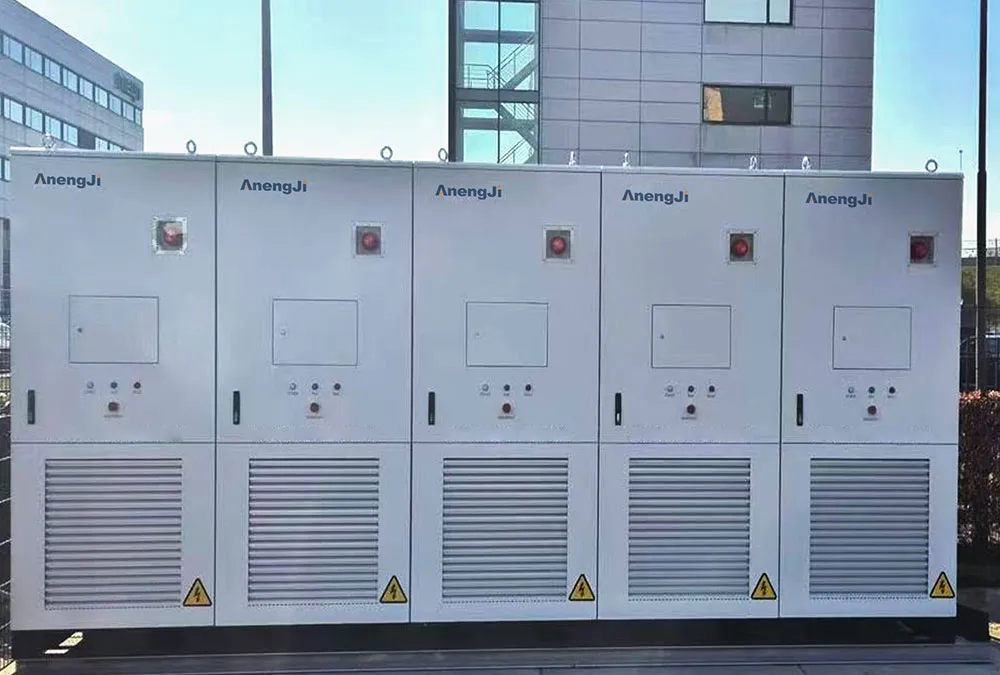
A manufacturing facility experiencing high peak demand penalties installed five outdoor liquid-cooled battery cabinets paired with a central 500 kW PCS and a dedicated step-up transformer skid. The system tied into the facility’s 11 kV service entrance to provide automated peak shaving and time-of-use energy arbitrage.
Operating Strategy and Engineering Results
The site EMS monitors building power draw via CT meters at the main utility entrance. When facility consumption exceeds 800 kW during afternoon production runs, the EMS signals the PCS to discharge up to 500 kW into the plant busbar within 50 milliseconds. This caps total grid draw under 800 kW, lowering monthly utility demand charges by over $6,200 while maintaining a strict zero-export mode to comply with local utility requirements.
Regional Grid Connection Requirements: Key International Differences
Interconnection requirements vary across regional energy markets. Engineering teams must adapt technical submittals to local utility frameworks.
- Europe (EN 50549 / VDE-AR-N 4110): Mandates strict low-voltage and medium-voltage ride-through parameters, precise active power curtailment curves, and certified grid-code compliance documentation for inverter equipment.
- North America (IEEE 1547 / UL 1741 SB): Requires UL-listed smart inverters capable of dynamic voltage support, anti-islanding protection, and compliance with local utility rulebooks (such as California Rule 21 or ISO-NE interconnections).
- Singapore & Southeast Asia (EMA Guidelines / IEC Standards): According to the official Energy Market Authority (EMA) Technical Guidelines, grid-tied battery storage installations must meet rigorous fire safety containment guidelines, mandatory thermal runaway propagation tests under UL 9540A Test Protocols, and dynamic reactive power control to secure energization clearance.
Documents Every BESS Buyer Should Request Before Interconnection
To safeguard project investments, ensure your system supplier or EPC contractor delivers a complete engineering submittal package prior to utility submission.
Essential Interconnection Document Checklist:
- Electrical Single-Line Diagram (SLD) with stamped engineer seal
- PCS Equipment Data Sheet showing grid-code certifications (IEEE 1547 / UL 1741)
- Factory Acceptance Test (FAT) reports for battery, BMS, and PCS units
- Protection Relay Settings and Coordination Curve Study
- EMS Control Logic Description & Zero-Export Safeguard Plan
- Step-Up Transformer & Switchgear Technical Specifications
- UL 9540A Fire Safety Test Summary Reports
Common BESS Grid Connection Mistakes to Avoid
- Purchasing Battery Racks Before Utility Review: Procuring hardware before verifying utility feeder capacity can leave equipment sitting unused if grid upgrades are required.
- Assuming Battery Capacity Equals Grid Export Rights: Conflating battery energy ratings with utility-approved AC export power limits causes commissioning disputes.
- Neglecting Short-Circuit Current Ratings: Failing to verify existing switchgear short-circuit ratings before adding inverter capacity creates safety hazards during grid fault events.
- Deferring Protection Studies: Postponing protection relay coordination modeling until late in construction frequently causes utility witness test failures.
Why AnengJi Is Your Strategic BESS Grid Interconnection Partner
Navigating commercial energy storage deployments requires a partner with deep expertise in power conversion, electrochemical storage, and grid protection. AnengJi delivers integrated battery energy storage solutions designed to simplify grid compliance for commercial, industrial, and EV infrastructure applications.
Our factory pre-tested 100 kWh to 1 MWh+ containerized and cabinet storage systems arrive pre-configured to streamline field commissioning. By matching high-efficiency LFP battery systems with advanced EMS control architectures, AnengJi helps site owners minimize grid connection delays, protect facility equipment, and maximize long-term return on investment.
Request a Technical BESS Grid Connection Assessment
Planning a commercial energy storage installation? Share your facility Single-Line Diagram, load profile, or transformer specs with our engineering team for a preliminary grid connection review.
 https://anengjipower.com/wp-content/uploads/2026/06/epc-vs-turnkey-solar-project-bess.webp
675
1000
Charging Station Engineer
https://anengjipower.com/wp-content/uploads/2025/09/anengji-dc-fast-charging-station-manufacturer-and-supplier-logo-white-1.png
Charging Station Engineer2026-06-22 07:16:042026-06-24 07:13:17What Is the Difference Between EPC and Turnkey Contract Models in Energy Projects?
https://anengjipower.com/wp-content/uploads/2026/06/epc-vs-turnkey-solar-project-bess.webp
675
1000
Charging Station Engineer
https://anengjipower.com/wp-content/uploads/2025/09/anengji-dc-fast-charging-station-manufacturer-and-supplier-logo-white-1.png
Charging Station Engineer2026-06-22 07:16:042026-06-24 07:13:17What Is the Difference Between EPC and Turnkey Contract Models in Energy Projects? https://anengjipower.com/wp-content/uploads/2026/06/anengji-commercial-solar-plus-storage-benefits-site.webp
675
1000
Charging Station Engineer
https://anengjipower.com/wp-content/uploads/2025/09/anengji-dc-fast-charging-station-manufacturer-and-supplier-logo-white-1.png
Charging Station Engineer2026-06-20 14:34:102026-06-20 14:37:43What Are the Top Benefits of Solar Battery Storage in Factories?
https://anengjipower.com/wp-content/uploads/2026/06/anengji-commercial-solar-plus-storage-benefits-site.webp
675
1000
Charging Station Engineer
https://anengjipower.com/wp-content/uploads/2025/09/anengji-dc-fast-charging-station-manufacturer-and-supplier-logo-white-1.png
Charging Station Engineer2026-06-20 14:34:102026-06-20 14:37:43What Are the Top Benefits of Solar Battery Storage in Factories? https://anengjipower.com/wp-content/uploads/2026/06/modular-commercial-solar-battery-storage-cabinet.webp
675
1000
Charging Station Engineer
https://anengjipower.com/wp-content/uploads/2025/09/anengji-dc-fast-charging-station-manufacturer-and-supplier-logo-white-1.png
Charging Station Engineer2026-06-18 09:16:522026-07-03 03:05:13What Is Solar Battery Storage? Complete C&I Engineering Guide
https://anengjipower.com/wp-content/uploads/2026/06/modular-commercial-solar-battery-storage-cabinet.webp
675
1000
Charging Station Engineer
https://anengjipower.com/wp-content/uploads/2025/09/anengji-dc-fast-charging-station-manufacturer-and-supplier-logo-white-1.png
Charging Station Engineer2026-06-18 09:16:522026-07-03 03:05:13What Is Solar Battery Storage? Complete C&I Engineering Guide

Leave a Reply
Want to join the discussion?Feel free to contribute!