
Introduction
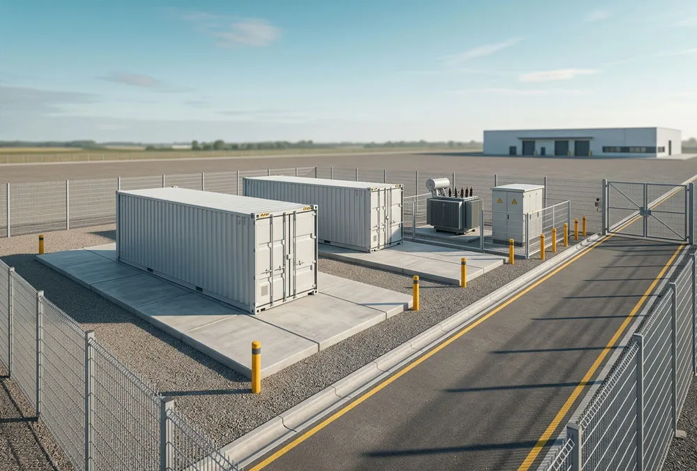
A quotation can say “RMU included” and still leave an EPC team with a difficult question two weeks before energisation: who owns the protection relay, CT/VT data, MV cable termination, remote-trip interface and site test? That is why RMU BESS is more than a component-definition search. A Ring Main Unit (RMU) is medium-voltage switchgear in the AC path of a battery energy storage system. It commonly sits between the BESS step-up transformer and the MV collection cable, where it can switch, isolate and earth the local transformer connection. Depending on the specified design, it can also include protection, metering inputs and remote-control functions.
RMU Explained in 30 Seconds
Think of the RMU as the controlled MV doorway for one BESS block. The battery stores energy; the PCS converts it; the transformer raises the voltage; the RMU is where that transformed power can be connected, isolated and made safe before it enters the site’s MV network.
- For an owner: it affects availability, safety boundaries and future costs.
- For an EPC: it defines cable, protection, control and test interfaces that must not be left between suppliers.
- For an engineer: it must match the approved topology, fault duty and network-operator requirements.
For European projects, this interface is becoming a procurement decision as well as an electrical one. Regulation (EU) 2024/573 on fluorinated greenhouse gases sets dates affecting new medium-voltage switchgear that uses, or relies on, fluorinated gases: the prohibition covers equipment up to and including 24 kV from 1 January 2026, and equipment above 24 kV to 52 kV from 1 January 2030, subject to the regulation’s conditions and exceptions. In plain terms: before choosing a compact MV cabinet, a European buyer should know its voltage class, insulation medium, delivery date and regulatory route. Leaving those questions until after equipment selection can create a compliance, lead-time and interface risk at the same time.
This guide starts with the simple picture, then adds the engineering detail only where it changes a decision. You will see where an RMU sits in a BESS, when a ring, chain or radial layout changes its duty, what “included” should mean in an RFQ, and how to verify the complete MV interface before site commissioning. It is not a substitute for the approved single-line diagram (SLD), the distribution system operator’s connection conditions, an authorised switching procedure or a project-specific protection study.
The practical rule: do not approve an RMU from a brochure description. Approve a defined MV interface: bays, ratings, protection, control, cable limits, earthing, testing and a named owner for every boundary.
What an RMU Does in BESS
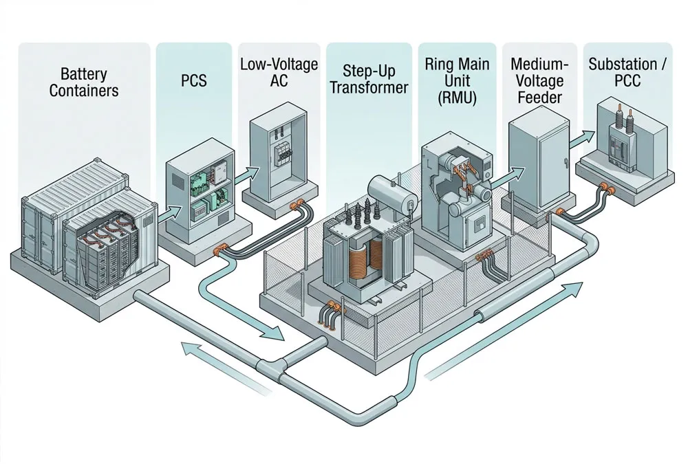
At its simplest, an RMU is the medium-voltage gate between a local BESS transformer and the site collection system. The PCS converts battery DC power into low-voltage AC. A transformer then raises that voltage to the project’s MV level. The RMU is the equipment that lets the transformer feeder be connected, disconnected and made safe within that MV network.
If you are new to MV design, the terms can sound more complicated than the purpose. Medium voltage (MV) is the part of the electrical system above normal low-voltage building distribution and below the high-voltage transmission grid. Isolation means creating a defined separation so a section can be safely taken out of service under the project’s approved procedure. Earthing means connecting the isolated section to earth as required by that procedure. The RMU helps create those controlled conditions; it is not a battery-management device and it does not decide when the battery should charge or discharge.
That plain explanation matters because component names are often blurred in early proposals. A PCS is not an RMU; a transformer is not an RMU; and a main MV switchboard is not automatically the same thing as a local RMU. They work as a chain, but they have different duties. IEC 62271-200:2021, the International Electrotechnical Commission’s standard for AC metal-enclosed switchgear and controlgear, applies to assemblies above 1 kV and up to 52 kV. It provides a useful scope reference; it does not prove that a particular offered RMU has the correct rating, internal-arc classification or type-test evidence for your project.
| Component | Primary job | What it does not automatically include | Buyer consequence |
|---|---|---|---|
| PCS | Bidirectional DC/AC conversion and AC power control. | MV isolation, feeder switching or the MV collection arrangement. | Do not let “PCS package” hide an undefined MV boundary. |
| Step-up transformer | Raises PCS output voltage to the MV system. | Feeder isolation, protection coordination or DSO control functions. | Transformer data must feed the protection and fault-level design. |
| RMU | Local MV switching, isolation and earthing; other functions are configuration-dependent. | A complete grid-connection approval, remote-control scheme or civil installation. | The bay schedule and interfaces, not the name “RMU,” define the scope. |
| Main MV switchboard | Aggregates feeders and may hold site-level protection. | A skid-level isolation point next to each transformer. | Clarify where local and site-level protection responsibilities meet. |
The suggested phrase “PCS in solar system” belongs to a different search task. The PCS is upstream in this electrical chain, and a solar-plus-storage project may share controls or a point of connection, but a reader searching for an RMU needs the MV switching and interface decision—not a second PCS explainer.
A useful first question: “At which drawing point does the BESS supplier stop and the site MV system begin?” If the answer changes between the quotation, SLD and contract schedule, resolve that mismatch before the order—not during commissioning.
RMU Location in an MV BESS
A useful functional path is: battery → PCS → low-voltage AC → step-up transformer → RMU → MV cable / collection feeder → substation or PCC. The equipment may be supplied as a PCS-and-transformer skid, a separate MV skid, or individual field-installed items. The packaging changes, but the electrical questions do not.
The published AECOM Gate Burton Energy Park BESS and Substation Description illustrates this system reality: its project description lists RMUs beside PCS units, transformers, power and control cabling, CT/VT metering and a control/SCADA point. That document is not a universal BESS layout. It does show why a proposal cannot be assessed by container capacity alone: the MV path depends on several connected packages and records.
This is where owners and EPCs can lose time. A general arrangement may place the transformer beside the RMU and make the arrangement look complete, while the electrical battery limits remain unmarked. Before a purchase order, ask each party to mark the handover point for power cable, fibre, auxiliary supply, earthing conductor, foundation, drainage, lifting access and commissioning records. If a point has no owner, it is a future variation waiting for a site meeting.
RMU Topology and Through-Current
Radial, chain or ring?
“Ring Main Unit” can be misleading. A BESS may use an RMU in a radial feeder, a daisy-chain collector or a looped/ring arrangement. The name does not prove that the plant operates as a closed ring, nor does it guarantee redundancy. The approved SLD and the network operating philosophy decide that.
| Layout | Potential RMU role | Question before specification | Commercial consequence |
|---|---|---|---|
| Radial | Local transformer isolation; pass-through bays may not be required. | Is every feeder, cable route and main-switchboard bay included? | More dedicated cable and upstream switchgear can change civil and electrical scope. |
| Daisy-chain | The local transformer can be isolated while the MV cable continues downstream. | What is the upstream RMU and cable’s maximum continuous through-current? | Identical-looking RMUs can have different duty by location. |
| Ring / loop | Can support a planned alternate feed path where protection and operations allow it. | Who owns the normal-open point, fault isolation and switching authority? | Cable-level resilience has a cost and must be proven through the operating philosophy. |
Here is a quick screening calculation, not a selection method. For a balanced three-phase MV circuit, approximate current is I = S ÷ (√3 × V), where S is apparent power in VA and V is line-to-line voltage in V. A 5 MVA block at 20 kV produces roughly 144 A at nominal apparent duty. Four such blocks downstream of one upstream RMU would indicate roughly 577 A before the full design checks. This does not establish an RMU rating. The actual decision needs the approved voltage class, maximum active and reactive duty, cable thermal limit, short-time withstand, fault level, transformer impedance, protection coordination, ambient conditions and the network operator’s requirements.
That upstream-current issue is a detail experienced project teams look for. “One RMU per skid” does not mean every RMU has the same continuous-current duty. If the project treats every skid as an identical plug-in block without checking feeder position, the nearest RMU to the substation can become the overlooked constraint. Ask for a feeder loading schedule and a normal / contingency operating diagram, not only a repeated equipment datasheet.
What this means in a design review:
- Point to the RMU closest to the substation on the SLD.
- Ask for its normal and contingency current duty, including every downstream block.
- Check that its rating, cable route and protection concept are assessed together—not as three separate purchase items.
RMU Protection and Isolation
Switch, fuse or breaker?
An RMU may contain load-break switching, a fused transformer feeder, a circuit breaker with a protection relay, or another project-specific arrangement. These options are not interchangeable marketing upgrades. A load-break switch performs normal load switching; a protection solution must be assessed against the fault and protection philosophy; and a circuit-breaker-plus-relay arrangement changes the control, settings and test obligations. The correct choice depends on fault level, transformer rating and impedance, required selectivity, remote operation, maintainability and the conditions at the point of connection.
A quick way to read this is: the switch changes the normal connection state, the fuse or relay scheme responds to specified fault conditions, and the circuit breaker is a controlled interrupting device used where the protection design requires it. The exact arrangement is not chosen by one label on a data sheet. It is chosen by the electrical study and the connection conditions. If a supplier uses the word “protected,” ask: protected against which condition, by which device, with whose settings, and who tests it?
Earthing is an operating step
Isolation and earthing are related but different. Opening a feeder is not, by itself, permission to work. The approved safety procedure must establish isolation, apply earths where required, control keys/interlocks and define the authorised person’s responsibilities. IEC 62271-200 addresses metal-enclosed switchgear assemblies and includes earthing-circuit and internal-arc test topics, but it cannot replace the project’s safe-system-of-work or demonstrate the final site arrangement.
For the buyer, the test is simple: can the supplier show the protection philosophy, trip matrix, control-power source, interlock narrative and relay I/O alongside the SLD? If the answer is only “protection included,” the commercial scope is too vague. Resolve it before factory release, when a drawing change is manageable—not after cables are dressed and the network operator is waiting for a witness test.
What “RMU Included” Must Cover
This is the point at which a definition page becomes useful for a project. “RMU included” should be converted into an inclusion/exclusion table before technical and commercial approval. A component schedule is not enough because the last metre of cable, one missing control contact or an undefined CT polarity can hold up the whole MV interface.
| Scope item | Decision to record | Evidence to request | Why it matters |
|---|---|---|---|
| Bays and electrical ratings | Included, excluded or by others. | Datasheet, bay schedule and approved SLD. | Stops a generic 2+1 label replacing real feeder duties. |
| Protection, CT/VT and metering | Who supplies, sets, tests and owns the data? | Protection philosophy, CT/VT ratios/classes/burdens and relay-setting responsibility. | A wrong ratio, polarity or setting can invalidate a functional test. |
| Remote and local control | Motorisation, local/remote authority and loss-of-comms behaviour. | I/O list, cause-and-effect matrix and communications boundary. | Prevents conflicting commands between DSO, SCADA, EMS and local controls. |
| Cables and terminations | Cable, connector, gland, lug and test scope. | Cable schedule, terminal schedule and test plan. | “By others” is acceptable only when the other party is named and funded. |
| Earthing and tests | Earthing boundary, FAT, SAT, witness and acceptance criteria. | Earthing drawing, interlock narrative and test responsibility matrix. | Turns a supplied cabinet into an accepted site interface. |
The specialist detail worth surfacing early is that the RMU can arrive fully wired internally and still be uncommissionable. The project may be missing a relay-settings file, a CT/VT polarity confirmation, a trip-coil control supply, a separable connector kit, a DSO intertrip contact or an agreed test owner. None of those omissions is visible in a glossy container render. A responsibility matrix and end-to-end I/O register expose them while there is still time to design them out.
You do not need to be a protection engineer to spot the warning signs. In a bid review, pause when a critical item is described only as “if required,” “interface available” or “by others.” Those phrases are not automatically wrong. They become risky when the quotation does not name which party, which drawing, which test and which acceptance record will close the gap.
Planning a containerised BESS package? Even when starting with a commercial and industrial battery storage configuration, the battery enclosure, PCS, transformer and RMU should be evaluated as one electrical path, even when they are supplied under separate scopes. Share the preliminary SLD, connection voltage and operating target to identify the MV questions before RFQ release.
Europe and Germany Requirements
Germany: connection rules first
For a German MV-connected BESS, start with the connection architecture and the responsible network operator—not the RMU catalogue. VDE FNN’s Technical Connection Rules for Medium-Voltage (VDE-AR-N 4110) state that their scope covers planning, erection, operation and modification of customer installations connected to the medium-voltage grid, including storage and combined generation/demand/storage facilities. The VDE rule helps define the national technical framework; the applicable DSO documentation and connection agreement still establish the project route.
In other words, an RMU can support the required interface, but it does not make a BESS grid compliant on its own. Protection settings, reactive-power behaviour, metering, control signals, operating permissions and witnessing can remain outside the equipment supplier’s package. The practical solution is to issue the DSO data and connection conditions with the RFQ, then require each bidder to mark compliance, assumptions, exclusions and interfaces against them.
Europe: choose the gas early
For Europe, ask what insulating and interrupting medium the proposed switchgear uses before the technical selection is frozen. The European Commission’s F-gas switchgear guidance tells operators to consider the new restrictions when planning new switchgear and highlights obligations around qualified personnel, records and recovery where relevant. This is not a reason to label every existing SF₆ installation non-compliant. It is a reason to add the voltage class, gas declaration, planned energisation date and regulatory assessment to a European RMU bid comparison.
United States projects should not import German or EU requirements by default. Their utility, authority having jurisdiction, interconnection agreement and applicable standards determine the route. The transferable lesson is the process: specify the MV interface from the actual connection requirements, then make the RMU vendor show the evidence for that exact duty.
FAT and SAT Prove the Interface
FAT proves the supplied assembly
A factory acceptance test (FAT) should demonstrate that the supplied RMU matches the approved configuration before shipment: identification, bay arrangement, mechanical operations and interlocks, protection hardware, internal control wiring, signal mapping and agreed documentation. FAT is valuable because it catches a mismatch when the equipment is accessible and the responsible supplier is present. It does not prove the final cable route, the site earthing system, DSO control link or the end-to-end BESS trip path.
SAT proves the site relationship
A site acceptance test (SAT) closes the interfaces. The project test plan should identify the authorised parties and the evidence for cable tests, protection and metering data, intertrip, local/remote command authority, SCADA status and alarms, PCS-transformer-RMU cause-and-effect, emergency-stop logic and written pass criteria. It should not publish a generic live-switching sequence; site switching belongs to authorised personnel acting under approved procedures.
This is a common point of friction for a developer: the PCS vendor proves the PCS, the switchgear vendor proves the cabinet, and the EPC proves the cable—but no party proves the whole trip chain. Make the final witness test an explicit contract deliverable. Name who initiates each signal, who observes it, the allowed response and the record that closes the test. That turns “all equipment supplied” into a testable plant interface.
Do not confuse a cabinet test with a plant test. FAT answers “was the ordered RMU built correctly?” SAT answers “does this RMU work correctly with this transformer, this cable, this PCS and this site-control system?” A reliable handover needs both answers.
RMU BESS RFQ Checklist
Before releasing an RFQ, ask the electrical lead to confirm these items against the current design—not a previous project:
- Grid voltage, frequency, fault-level data and point-of-connection boundary.
- BESS active/reactive duty, transformer rating and impedance, including the duty of each feeder location.
- Radial, chain or ring topology, plus normal-open point and switching responsibility where applicable.
- Required bays, rated voltage/current, short-time withstand and defined future expansion need.
- Protection philosophy, CT/VT data, relay settings owner, metering boundary and DSO interfaces.
- Insulation / interrupting medium and the applicable European F-gas review.
- Environmental, access, internal-arc, earthing, civil, drainage and cable-entry requirements relevant to the site.
- Remote-control protocol, cyber boundary, local/remote authority and loss-of-communications behaviour.
- Required deliverables: SLD, general arrangement, data sheets, project-required test evidence, FAT/SAT plan, as-builts and training records.
If a bidder cannot complete this list, that does not automatically make the offer unsuitable. It means the proposal is still a budgetary equipment concept rather than a defined MV package. Make the unknowns visible, assign an owner and value them before comparing prices.
RMU in BESS FAQs
What is an RMU in a BESS?
An RMU is medium-voltage switchgear used at the interface between a BESS transformer and the MV collection network. Depending on configuration, it provides switching, isolation, earthing and specified protection, metering or remote-control functions.
Is an RMU the same as a transformer?
No. The transformer changes voltage. The RMU manages the MV switching and safe isolation interface around that transformer. Both may be mounted in one package, but their functions and test records are different.
Does every BESS need an RMU?
No universal rule applies. The connection voltage, plant size, collection topology, protection philosophy and network-operator requirements determine whether an RMU or another MV switchgear arrangement is appropriate.
What does “RMU included” mean?
It is incomplete until the SLD, bay schedule, electrical ratings, protection/metering/control scope, cable and termination boundary, earthing, FAT/SAT responsibility and exclusions are named.
Does an RMU make a BESS grid compliant?
No. It is one part of the MV interface. Grid compliance still depends on the applicable connection rules, utility/DSO conditions, studies, protection settings, controls, tests and approvals.
Confirm Your MV Scope Early
Share your planned connection voltage, preliminary single-line diagram, PCS/transformer arrangement, operating objective and DSO status. AnengJi can help identify the BESS package boundaries and technical questions to resolve before procurement. Final protection studies, approvals and operating procedures remain project-specific engineering deliverables.
 https://anengjipower.com/wp-content/uploads/2026/06/epc-vs-turnkey-solar-project-bess.webp
675
1000
Charging Station Engineer
https://anengjipower.com/wp-content/uploads/2025/09/anengji-dc-fast-charging-station-manufacturer-and-supplier-logo-white-1.png
Charging Station Engineer2026-06-22 07:16:042026-06-24 07:13:17What Is the Difference Between EPC and Turnkey Contract Models in Energy Projects?
 https://anengjipower.com/wp-content/uploads/2026/06/anengji-commercial-solar-plus-storage-benefits-site.webp
675
1000
Charging Station Engineer
https://anengjipower.com/wp-content/uploads/2025/09/anengji-dc-fast-charging-station-manufacturer-and-supplier-logo-white-1.png
Charging Station Engineer2026-06-20 14:34:102026-06-20 14:37:43What Are the Top Benefits of Solar Battery Storage in Factories?
 https://anengjipower.com/wp-content/uploads/2026/06/modular-commercial-solar-battery-storage-cabinet.webp
675
1000
Charging Station Engineer
https://anengjipower.com/wp-content/uploads/2025/09/anengji-dc-fast-charging-station-manufacturer-and-supplier-logo-white-1.png
Charging Station Engineer2026-06-18 09:16:522026-07-03 03:05:13What Is Solar Battery Storage? Complete C&I Engineering Guide


Leave a Reply
Want to join the discussion?Feel free to contribute!