

Introduction
A proposal can say “1 MW BESS PCS” and still be wrong for your project. It may deliver 1 MW only at a particular voltage, have limited reactive-power headroom, accept a different battery DC-voltage window, derate at the site’s summer temperature, or exclude the transformer, switchgear, controls and test work needed at the point of connection. For an EPC team or owner-side engineer, that is not a catalogue-detail problem. It is how a low-looking equipment price becomes a grid-connection delay, an unplanned variation order, or a battery that cannot perform the duty it was bought for.
This guide explains what a BESS PCS does, but more importantly, how to turn the term into a comparable project requirement. The focus is Europe first, with Germany used to show why PCS evidence belongs in the grid-connection conversation. The same engineering logic is useful in the United States and elsewhere, but the applicable connection rules and acceptance route remain local.
Direct answer: a Power Conversion System is the bidirectional electrical interface that moves energy between the battery’s DC domain and the site or grid AC domain. In a real project, it also carries the power-quality, operating-mode, protection and control requirements that determine what the BESS can actually deliver. A PCS is therefore more than a battery inverter, and its nameplate MW is only one part of the decision.
What Is a BESS PCS?
Battery cells store and release direct current. Buildings, industrial distribution systems and public grids normally operate on alternating current. The European Commission’s Clean Energy for EU Islands technical-assistance report explains that a PCS enables DC-to-AC supply to a load or grid and AC-to-DC charging. The same report describes the EMS as the higher-level system that schedules operation while communicating with the BMS and PCS. Those are distinct jobs, and mixing them up is a common source of incomplete specifications.
If you are new to the terminology, use this simple picture: the battery is where energy is stored; the BMS keeps the battery inside its safe limits; the PCS is the controlled gate that turns battery energy into usable AC electricity and lets AC electricity charge the battery; the EMS decides when that gate should move power. The real project becomes more complex because the PCS must also work with switchgear, a transformer, protection relays, meters and the grid operator’s requirements.
| Term | Project role | What it does not establish on its own | Buyer check |
|---|---|---|---|
| Inverter | A power-electronic building block that converts DC to AC; in battery service it is normally bidirectional. | The complete protection, filtering, control, auxiliary and AC/MV package. | Ask what equipment is included around the inverter modules. |
| PCS | The conversion system that controls bidirectional power and may include conditioning, protection and grid-interface functions. | That transformer, LV/MV switchgear, PPC or SCADA integration are all in the supplied scope. | Request the single-line diagram, general arrangement and scope boundary. |
| BMS | Monitors the battery and applies battery safety/operating limits. | The site dispatch strategy or grid-support duty. | Confirm the BMS-to-PCS limit and fault-interface definition. |
| EMS / PPC | Schedules energy and coordinates plant-level set-points, subject to available hardware and grid constraints. | That the PCS can exceed its electrical envelope to fulfil a command. | Define command ownership, latency, fallback and export-limit logic. |
The U.S. Department of Energy’s BESSIE supply-chain report makes the same distinction: it describes PCS as the wider conversion and power-conditioning system, potentially incorporating multiple inverters plus control and protection. For a buyer, the practical conclusion is simple: “PCS included” is not a complete scope line unless the DC boundary, AC boundary and interface responsibilities are named.
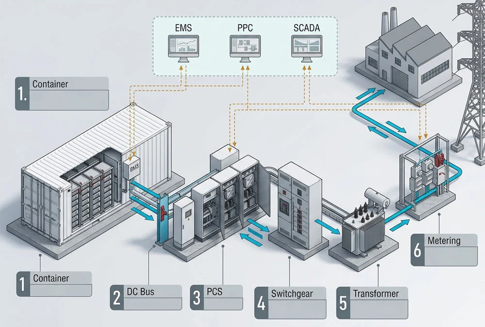
How to Choose the Right PCS
Before comparing efficiency, container count or unit price, test the proposal against the eight checks below. This is the PCS Procurement Envelope: the operating and interface boundary within which a supplier’s stated performance must remain true. It makes quotations comparable without pretending that one PCS architecture suits every C&I, PV, microgrid or utility project.
You do not need to perform every electrical study yourself to use this list. Its purpose is to help an owner ask the right questions and help an EPC request the right evidence. If a supplier cannot define one of these boundaries, the honest result is “data still needed”—not a confident-looking but incomplete performance promise.
| Check | Why it changes the PCS choice | Evidence to request | Buyer benefit |
|---|---|---|---|
| 1. AC duty | Required MW, MVA, voltage, power factor and duration decide the AC delivery envelope. | Continuous/temporary P-Q curve at the declared voltage and ambient condition. | Avoids buying a MW label that cannot meet the actual grid-support duty. |
| 2. DC acceptance | Battery voltage and current change with configuration, SOC and conditions. | Minimum, nominal and maximum DC voltage; charge/discharge current; BMS interface. | Prevents a battery–PCS mismatch hidden by a nominal DC-voltage class. |
| 3. Operating mode | Grid-following and grid-forming have different reference, transition and protection requirements. | Mode description, limits, plant sequence and test scope. | Stops an unsupported backup, islanding or black-start promise. |
| 4. Grid quality | Harmonics, ride-through, voltage/frequency and protection duties are connection-specific. | Relevant DSO/TSO requirement, studies and capability evidence. | Keeps compliance evidence tied to the actual project rather than a brochure. |
| 5. Efficiency boundary | Losses can be measured at the PCS terminals, transformer side or PCC. | Test boundary, load map, auxiliary assumptions and annual model. | Makes “efficient” bids comparable on the same basis. |
| 6. Thermal duty | Ambient temperature, ventilation and continuous operation may reduce available output. | Derating curve, cooling auxiliaries, altitude and noise assumptions. | Protects the duty you expect at the hottest or most demanding hour. |
| 7. Physical package | Central, string, standalone and PCS-MV skid arrangements shift installation and availability boundaries. | SLD, general arrangement, equipment inclusion/exclusion list and FAT scope. | Reveals missing transformer, switchgear, cabling or civil scope before award. |
| 8. Data and safety interfaces | PCS behaviour depends on BMS limits, EMS/PPC commands, meters, relays, SCADA and emergency trips. | I/O list, protocol map, responsibility matrix and SAT procedure. | Limits commissioning disputes between battery, PCS, MV and controls suppliers. |
PCS Power Rating: MW vs MVA
Think of PCS capacity as one electrical budget. Active power (MW) is the energy-moving part: it charges or discharges the battery. Reactive power (MVAr) helps manage voltage, but it can use some of the same PCS capacity. That is why a PCS rated at 1 MW is not automatically available for 1 MW of discharge while also supplying every reactive-power requirement. In a simplified steady-state screen, S = √(P² + Q²), where S is MVA, P is MW and Q is MVAr. If an illustrative duty calls for 1.0 MW and 0.5 MVAr at the same moment, the calculated apparent-power demand is about 1.12 MVA before project-specific margins and limits. This is only a screening calculation; the PCS manufacturer’s P-Q capability curve at the actual AC voltage, temperature and control mode decides what the unit can sustain.
The buyer problem is familiar: one bidder quotes only MW while another includes an MVA/P-Q envelope, and both proposals appear equivalent. If voltage support, power-factor control or grid-service duty matters, make the P-Q curve a bid requirement. It gives the EPC a defensible basis for transformer, cable and switchgear checks as well as PCS comparison.
PCS DC Input Range
On the DC side, do not select a PCS because both data sheets say “1,000 V class” or “1,500 V class.” The usable battery voltage window can move with battery configuration, SOC, temperature and operating limits. The correct request is a matched interface sheet: minimum, nominal and maximum DC voltage; maximum charge and discharge current; short-circuit/protection information; and the BMS-to-PCS communications and interlock definition. This is not extra paperwork. It is the evidence that the selected conversion equipment can control the actual battery across its authorised operating range.
PCS in Solar + Storage
The phrase PCS in solar system can mean several different physical arrangements. In plain terms, a solar inverter takes electricity from the PV panels and makes AC power. A battery PCS moves power into or out of the battery. They may meet on the AC side, or the battery and PV may share DC-side equipment in another architecture. The important early question is not which label sounds more efficient. It is where PV, battery, load, meter and point of common coupling meet—and what import/export limit applies there.
This is where an otherwise good solar-plus-storage proposal can disappoint an owner. The system may have enough battery energy, but an existing PV inverter, transformer, PCC capacity or export agreement can cap the combined plant. Before recommending PCS power, collect interval load and PV data, the existing single-line diagram, the written import/export envelope, transformer details and the meter/control arrangement. The site’s grid-connection decision guide provides the wider battery-to-PCC chain; this article narrows the task to what the PCS must deliver inside that chain.
A separate decision remains whether the overall PV+BESS plant should be AC-coupled or DC-coupled. That is an architecture and commercial question, not a reason to assume every PCS has the same connection rights. Evaluate the topology after the PCC, existing equipment and operating objective are understood.
How PCS Efficiency Is Measured
PCS efficiency matters, but start with one simple question: where was the energy meter located when this percentage was measured? One supplier may report conversion at the PCS terminals. Another may include transformer losses, cooling, control power and auxiliary loads. A third may quote a favourable operating point that does not resemble your demand-charge, PV-shifting or grid-service duty cycle. None of those is automatically wrong; they are simply not comparable until the boundary and profile match.
Use one named energy boundary: for a round-trip calculation, define ηpath = discharged energy measured at the chosen delivery boundary ÷ charging energy measured at the same boundary.
The calculation is only meaningful when the bid states whether the boundary is battery DC, PCS AC terminals, transformer MV side or PCC—and whether auxiliaries are included. It is an engineering comparison method, not a universal performance guarantee.
| Measurement boundary | Typically includes | Can omit | Buyer consequence |
|---|---|---|---|
| Battery DC | Battery-side energy movement. | PCS, transformer, AC cables and site auxiliaries. | Useful for battery analysis, not enough for a grid-delivered-energy promise. |
| PCS AC terminals | Battery and conversion path inside the stated PCS boundary. | External transformer, MV works and sometimes site auxiliaries. | Good for PCS comparison only if suppliers use the same boundary and duty map. |
| Transformer / PCC | More of the actual plant path to the grid or facility. | Depends on metering design and contractual definition. | Often closer to commercial value, but must be defined before guarantees are compared. |
The practical fix is to ask for an efficiency map or loss model across the expected power range, power factor, AC voltage and ambient conditions—then apply it to the project’s actual time series. That does more for an owner than arguing about a single headline percentage. It also exposes whether transformer and auxiliary losses are being assigned to the PCS supplier, the EPC scope or neither.
Grid-Following vs Grid-Forming
A grid-following PCS needs a healthy grid waveform to follow, much like a musician needs a conductor’s beat. A grid-forming PCS is designed to create or regulate that voltage-and-frequency reference under its specified conditions. The distinction matters for microgrids, islanding and some grid-support applications, but it is not a shortcut to promise backup or black start. Those outcomes also depend on isolation, switchgear, protection, auxiliaries, load sequence, controller settings and, where relevant, operator acceptance.
In Germany, VDE FNN’s Requirements for System Stability page identifies its current grid-forming-capability guideline and verification framework as the technical basis for grid-forming units in the related future inertia-market context. That supports a narrow but important point: grid-forming capability is a technical requirement-and-evidence question in Germany, not a generic marketing label. It does not establish that every PCS, project or country has the same qualification route.
If resilience is part of your business case, ask one direct question: what sequence is the PCS required to execute from the initial condition to the protected-load or handover point? A supplier should be able to identify the reference source, transfer/islanding philosophy, load steps, BMS limits, protection settings and test record. If those items are not defined, retain “backup” or “black start” as an unverified project objective rather than a promised PCS feature.
PCS Requirements in Germany
Europe is not one electrical-rulebook in practice. The relevant distribution system operator (DSO) or transmission system operator (TSO), voltage level, connection offer, measurement concept and project operating mode define what evidence must be produced. Germany is a useful example because VDE FNN’s storage-connection guidance states that its application rules set technical requirements for the connection and operation of energy storage at the relevant voltage level, in line with European specifications. The page also describes connection and measurement concepts for storage as a practical topic—not a secondary paperwork item.
For an EPC, the response is not to copy a rule number from another project. Start with the proposed PCC voltage, the relevant network operator, import/export rights, fault level, protection concept, meter/remote-control requirements and any requested voltage or frequency support. Then ask the PCS supplier which requirements are covered by equipment capability, which require plant-controller integration, and which require project-specific studies or operator approval.
The United States has its own utility, state and interconnection frameworks; an IEEE or utility document from a US proposal cannot demonstrate German conformity. Likewise, a German connection approach should not be sold as a universal US design. The transferable part is the evidence discipline: state the electrical boundary, the required response and the responsible party before award.
PCS Commissioning: Check Power Direction
A BESS is bidirectional. That sounds obvious until the project reaches factory acceptance testing. The meter, current transformers, PCS, EMS and SCADA all need the same interpretation of positive and negative power. If a current-transformer polarity or tag convention is reversed, the local display may simply show an unexpected sign. But an automated export limit or peak-shaving control loop can then respond in the wrong direction.
This is one of the details that experienced commissioning teams check before a site is live. A practitioner electrical-panel guide on bidirectional metering notes the same risk and recommends verifying the direction across the meter, EMS and SCADA rather than merely checking that a value appears on screen. Treat this as FAT good practice, not as a universal regulation: apply or inject a known import/export direction, then witness the sign, status and command response feeder by feeder. Record the agreed convention in the I/O list and control narrative.
The same discipline applies to the smaller interfaces that often disappear between packages: BMS limit signals, fibre or Ethernet terminations, emergency-stop loops, fire-system trips, auxiliary feeds and breaker-status feedback. They can be physically minor but commercially expensive after panels and containers are fabricated. The solution is a responsibility matrix that names who supplies, terminates, tests and accepts every cross-package signal.
PCS RFQ Checklist
A supplier can propose a meaningful PCS only when the electrical and operational inputs are visible. Include the following in the request for quotation:
- Target application, interval load/PV data, charge/discharge duty, reserve SOC and required response time.
- PCC voltage, contracted import/export limits, existing SLD, transformer data and available fault-level/protection information.
- Required active and reactive duty, including the voltage and ambient condition at which it must be delivered.
- Battery DC minimum/nominal/maximum voltage, current, BMS interface and authorised operating window.
- GFL/GFM, islanding, resilience or grid-service requirements written as a sequence and acceptance test—not a broad feature label.
- PCS package boundary: inverter modules, filters, DC equipment, LV/MV switchgear, transformer, RMU, auxiliaries, cabling and civil interfaces.
- Protection, metering, PPC/EMS/SCADA protocols, I/O ownership, cybersecurity boundary and sign convention.
- FAT/SAT tests, efficiency/performance measurement boundary, exceptions, warranty operating envelope and excluded studies/approvals.
This list does not make the RFQ bureaucratic. It prevents two bidders from solving different problems under the same heading. For broader project development, the site’s Europe-focused BESS design guide explains how the electrical, control, compliance and contractual boundaries connect. Where an integrated delivery route is required, AnengJi’s verified EPC configuration approach describes evaluating the PCS alongside battery, cooling, EMS and safety scope; the final PCS selection still requires project-specific inputs and validation.
BESS PCS FAQs
What is a PCS in a BESS?
A PCS is the bidirectional power-conversion system between the battery’s DC side and the AC grid or load. Depending on its package and project design, it also supports power control, protection, power quality and communication with plant controls.
Is a PCS the same as an inverter?
An inverter is a conversion building block. In BESS terminology, PCS normally refers to the wider bidirectional conversion equipment and may include controls, filtering, protection and other grid-interface functions. The exact package must be confirmed in the supplier scope.
How do MW and MVA affect PCS selection?
MW describes active power. MVA describes the combined active and reactive electrical duty. If the project needs voltage support or a specific power factor while delivering MW, evaluate the supplier’s P-Q capability curve and thermal limits at the required AC voltage.
PCS Reactive Power at Idle
Some PCS designs can control reactive power with little or no active-power transfer, but this is not a universal entitlement. The available range depends on the PCS capability curve, control mode, AC voltage, thermal state, connection agreement and plant controls. Request the applicable operating envelope.
Does Grid-Forming PCS Guarantee Backup?
No. Grid-forming capability may be necessary for an intended island or restoration mode, but backup also requires a suitable isolation and transfer arrangement, protected loads, auxiliary power, protection coordination, control logic and a tested operating sequence.
Select the PCS After the Electrical Duty Is Known
A PCS is not selected by one efficiency percentage or one MW number. Define the battery DC window, AC P-Q duty, operating mode, temperature, PCC requirements and interface scope first. Then ask suppliers to show the evidence that their proposed system will meet that same envelope.

 https://anengjipower.com/wp-content/uploads/2026/06/epc-vs-turnkey-solar-project-bess.webp
675
1000
Charging Station Engineer
https://anengjipower.com/wp-content/uploads/2025/09/anengji-dc-fast-charging-station-manufacturer-and-supplier-logo-white-1.png
Charging Station Engineer2026-06-22 07:16:042026-06-24 07:13:17What Is the Difference Between EPC and Turnkey Contract Models in Energy Projects?
 https://anengjipower.com/wp-content/uploads/2026/06/anengji-commercial-solar-plus-storage-benefits-site.webp
675
1000
Charging Station Engineer
https://anengjipower.com/wp-content/uploads/2025/09/anengji-dc-fast-charging-station-manufacturer-and-supplier-logo-white-1.png
Charging Station Engineer2026-06-20 14:34:102026-06-20 14:37:43What Are the Top Benefits of Solar Battery Storage in Factories?
 https://anengjipower.com/wp-content/uploads/2026/06/modular-commercial-solar-battery-storage-cabinet.webp
675
1000
Charging Station Engineer
https://anengjipower.com/wp-content/uploads/2025/09/anengji-dc-fast-charging-station-manufacturer-and-supplier-logo-white-1.png
Charging Station Engineer2026-06-18 09:16:522026-07-03 03:05:13What Is Solar Battery Storage? Complete C&I Engineering Guide


Leave a Reply
Want to join the discussion?Feel free to contribute!