
Introduction
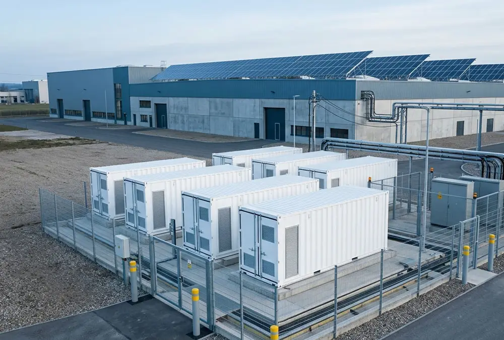
Adding AC-coupled battery storage beside an operating solar plant can preserve the existing PV inverter and much of the DC installation. That does not mean the project leaves the electrical system unchanged. The battery introduces a second bidirectional power-conversion path, and that path can affect import capacity, export capacity, switchgear, protection, metering and control at the point of connection.
Germany’s Federal Network Agency makes this distinction explicit in its storage grid-connection FAQ. Under the question addressing batteries as both generation and consumption facilities, the agency states that storage needs connection capacity for both withdrawal and feed-in, and that a physical grid connection does not automatically allocate the requested capacity. See the Bundesnetzagentur storage grid-connection FAQ. For an owner or EPC, the consequence is practical: “retrofit-friendly” must not be interpreted as “approval-free.”
Direct answer: an AC-coupled battery energy storage system connects the battery to a site’s AC network through its own bidirectional power conversion system (PCS). If solar PV is present, the PV inverter and battery PCS remain separate and meet on a common AC bus. This separation can simplify suitable retrofit and phased projects, but it adds AC-side equipment, conversion stages and control interfaces that must be engineered and tested.
What Is an AC-Coupled BESS and Where Is It Connected?
The term describes an electrical connection relationship, not a battery chemistry. Lithium-ion cells still store and release direct current. “AC-coupled” means the battery subsystem reaches the facility or grid through a dedicated PCS, while the PV array reaches the same AC network through its own PV inverter. Their power meets after conversion to AC rather than on a shared DC bus.
This is why the phrase is most useful in a solar-plus-storage or multi-source project. A standalone grid battery also connects to an AC network through a PCS, but calling it AC-coupled does not define the rest of its architecture. A project still needs a single-line diagram showing the battery strings, DC collection, PCS blocks, transformers, switchgear, meters, protection, auxiliary supply, controllers and point of connection.
The IEA Photovoltaic Power Systems Programme shows an AC-coupled PV-plus-BESS hierarchy in its material on operating reliability: PV and battery have distinct conversion paths, while performance data can be assessed at battery DC, BESS AC and combined PV-plus-BESS boundaries. Its 2026 summary also notes that topology, inverter behaviour, control logic, operating profile, temperature and firmware all affect real-world performance. Review the named findings in “Assessing the Reliability of Battery Systems in Solar Power Plants in Operation”.
Readers who need the wider system context can first review the battery energy storage system fundamentals. The present guide focuses on the coupling boundary and the decisions that follow from it.
AC-Coupled BESS Components: Battery, PCS, BMS, EMS and Grid Interface
A useful component list should show responsibility and measurement boundaries, not merely name hardware. In an AC-coupled battery system, the independent PCS is important, but the project succeeds only when the battery, controls, protection and site network operate as one coordinated installation.
| Component or boundary | Primary function | What the buyer should verify | Consequence if unclear |
|---|---|---|---|
| Cells, modules and racks | Store DC energy within defined voltage, current, temperature and state-of-charge limits. | Gross versus usable DC energy, duty cycle, operating window, environmental limits and warranty boundary. | The quoted MWh may not equal deliverable AC energy or required lifetime output. |
| Battery management system | Monitors cells and racks, estimates status and communicates permissible charge/discharge limits. | Protection hierarchy, data points, update rates, alarm/trip logic and PCS interface. | A high-level dispatch command may conflict with the battery’s actual safe operating limit. |
| Bidirectional PCS | Rectifies AC to DC during charging and inverts DC to AC during discharge; may also provide reactive-power and grid-support functions. | Continuous and short-term power, voltage, grid-code functions, efficiency map, operating modes and certification scope. | The BESS may meet its energy rating but fail the required power, voltage or connection behaviour. |
| Transformer, switchgear and protection | Connects the PCS to the facility bus or grid at the required voltage and isolates faults. | Thermal loading, fault levels, selectivity, earthing, isolation, auxiliary supply and ownership boundary. | Late equipment upgrades, nuisance trips or an installation that cannot be safely energised. |
| Meters and current transformers | Measure PV, load, BESS and grid exchange at defined boundaries. | CT ratio, direction, accuracy, location, time synchronisation and revenue-meter relationship. | The controller may react to the wrong power flow or fail to enforce the export limit. |
| EMS and plant controller | Schedules economic dispatch and regulates combined plant behaviour at the PCC. | Command priority, communications, fail-safe state, export control and loss-of-comms behaviour. | PV and BESS controls may compete, overshoot a limit or leave capacity unavailable. |
Meter and CT Placement in an AC-Coupled Battery System
A battery PCS cannot regulate what the controller does not measure correctly. If a current transformer excludes one PV feeder, has reversed polarity or reports at a different timestamp from the facility meter, the EMS may interpret export as load or miss simultaneous PV and battery output. The result may be incorrect charging, avoidable curtailment or an export-limit breach.
Resolve this before commissioning by marking every measurement point on the single-line diagram, defining the sign convention and then testing known charge, discharge, PV and load states during site acceptance. The German VDE FNN page on grid-compatible connection of energy storage specifically describes connection and metering concepts as configuration-dependent and links them to voltage-level technical connection rules.
How Does an AC-Coupled BESS Work? Four Power Flows
A single arrow from solar to battery hides the operating choices that determine yield, losses and compliance. An AC-coupled system can have at least four relevant paths.
| Operating path | Conversion sequence | Primary decision | Buyer consequence |
|---|---|---|---|
| PV to load or grid | PV DC → PV inverter AC → site load or PCC | Whether existing PV can continue operating independently of the BESS. | Battery downtime need not stop PV if the switchgear and controls preserve the path. |
| PV to battery | PV DC → PV inverter AC → battery PCS DC → battery | Whether surplus PV is visible and dispatchable at the common AC bus. | The business case must include both conversion stages and cannot assume access to energy clipped inside the PV inverter. |
| Grid to battery | Grid AC → transformer/site bus → battery PCS DC → battery | Whether connection terms, tariffs, incentives and controls permit grid charging. | A technically possible path may be commercially restricted or require additional import capacity. |
| Battery to load or grid | Battery DC → PCS AC → site load or PCC | Whether discharge serves self-consumption, peak control, market dispatch or export. | The required meter, response, reserve and connection limit change with the service. |
These paths also explain why one “system efficiency” number can be misleading. PV consumed directly by the facility does not pass through the battery. PV stored for later use passes through the PV inverter, the battery PCS during charging and the PCS again during discharge, plus cables, transformers and auxiliaries inside the declared test boundary. Grid-charged energy follows another path. A credible model assigns losses to the path the project will actually use.
Adding Battery Storage to an Existing Solar PV System
Which Existing PV Components Can Remain?
In a suitable retrofit, the PV modules, string wiring, DC combiner equipment and existing PV inverter may remain in service. This can reduce design disruption, preserve a functioning PV asset and avoid opening an existing DC system merely to add storage. Whether those elements can remain depends on their condition, remaining life, documentation, warranty, fault history and the proposed AC connection—not on the coupling label alone.
Which AC-Side Equipment Must Be Revalidated?
The battery PCS adds a controllable source and load to the facility network. The EPC may need to reassess transformer loading, switchgear ratings, protection coordination, fault current, earthing, harmonic performance, auxiliary supply, communications and the physical installation. Construction sequencing matters as well: a design that preserves the PV inverter can still require a planned outage to modify the main AC board.
The most expensive misunderstanding is to assume that the existing PV export approval automatically covers full battery discharge. At a common point of connection, the credible maximum may include simultaneous PV output and BESS output unless a tested controller enforces another operating envelope. An export cap can be a valid design feature, but the network operator must accept the arrangement and the project must define how it behaves during meter, communication or controller failure.
Germany Grid-Connection Checks for an AC-Coupled BESS
VDE FNN explains that German storage connection requirements are organised through voltage-level-specific Technical Connection Rules, with additional guidance covering practical connection and operating concepts. The Bundesnetzagentur FAQ separately states that requested import and export capacity must be addressed through the connection arrangement. Together, these sources support a simple procurement rule: confirm the permitted operating envelope before selecting PCS power.
Have an existing PV single-line diagram and a proposed battery rating?
A preliminary review can identify the likely connection, metering and control questions before suppliers build incompatible assumptions into their quotations.
Why C&I Projects Choose an AC-Coupled Battery System
AC coupling can create real project value, particularly where solar is already operating. The advantages are not automatic product characteristics; each depends on the electrical and commercial design.
| Potential advantage | Condition required | Buyer benefit | Evidence to request |
|---|---|---|---|
| PV retrofit flexibility | The existing PV asset is serviceable, and an AC connection point can accommodate the BESS. | Less PV-side redesign and potentially less disturbance to the operating array. | Existing SLD, condition review, warranty check and proposed tie-in drawing. |
| Independent sizing and replacement | PV and BESS equipment have defined interfaces and adequate connection headroom. | The battery PCS and PV inverter can follow different capacity and replacement cycles. | Interface matrix, spare capacity, future-expansion study and warranty boundaries. |
| Partial operational independence | Switchgear and controls allow one subsystem to remain available when the other is isolated. | Maintenance or a fault in one conversion path may not stop the other asset. | Operating-state matrix, isolation plan and failure-mode tests. |
| Flexible charge sources | Grid charging and PV charging are permitted and measurable under the project’s rules. | Dispatch can respond to solar surplus, tariffs or market signals instead of one fixed source. | Connection terms, tariff treatment, meter concept and EMS functional description. |
| Separate commercial operation | Contracts, meters and grid rights allow the PV and storage assets to be operated or financed separately. | Clearer asset responsibilities and potentially different revenue strategies. | Metering diagram, dispatch priority, revenue allocation and access rights. |
The UCL Energy Institute’s “Hybrid Storage Assets Briefing” explains on pages 8–9 that AC coupling has historically supported independent financing and operation of variable renewable generation and BESS. The same discussion also warns that shared-connection priorities can constrain battery dispatch and profitability. Independence of equipment therefore does not remove the need to define access to the common connection.
AC-Coupled BESS Disadvantages and Design Limitations
Conversion Losses in AC-Coupled Energy Storage
When PV energy charges the battery through the AC bus, it is converted from PV DC to AC, then from AC back to battery DC. It returns through the PCS as AC when discharged. That path normally carries more conversion loss than direct PV consumption and may carry more than a suitable shared-DC architecture. The correct comparison is not a marketing peak-efficiency value. Request efficiency curves at relevant loading, define whether transformer and auxiliary losses are included, and model annual energy through each path.
Can AC-Coupled Storage Recover PV Inverter Clipping?
If excess DC generation is clipped inside the PV inverter, that energy never reaches the common AC bus. An AC-side battery cannot store energy that was not converted to AC. This matters most when the business case relies heavily on recovering clipped production from an oversized PV array. Quantify that opportunity with timestamped irradiance or production data, the PV inverter loading ratio and the existing export limit; do not assume a generic percentage.
Additional Switchgear, Protection and Control Scope
An independent PCS may bring additional switchgear, transformer capacity, meters, protection, communications and maintenance interfaces. The architecture can still be the lower-risk retrofit option, but the decision should compare total installed scope and lifecycle operation—not inverter count alone.
Can an AC-Coupled BESS Provide Backup Power?
A frequent buyer assumption is that a battery with an inverter will continue supplying the factory when the grid fails. A grid-following PCS may instead disconnect as required when it loses the grid reference. Intentional island operation can require approved isolation or transfer equipment, a defined critical-load bus, grid-forming capability, black-start logic, earthing arrangements and coordinated behaviour from the PV inverter.
Define backup as a separate operating state. Specify which loads must remain energised, their starting and transient power, the required duration, how the island is formed, whether solar may continue operating, how the system returns to grid-parallel service and how the complete sequence will be tested. “Backup-ready” is not an acceptance procedure.
AC-Coupled BESS Grid-Connection Requirements in Europe and the US
Europe is not one connection regime. EU legislation and European network frameworks influence the market, but the applicable technical requirements, certification process, connection agreement, meter arrangement and approval sequence depend on the country, voltage level and network operator. The United Kingdom must also be assessed separately from EU-27 member states.
| Decision area | Germany example | Other EU-27 projects | United Kingdom | United States |
|---|---|---|---|---|
| Connection capacity | Confirm withdrawal and feed-in capacity plus the contractual operating envelope. | Confirm national and DSO allocation rules; do not copy the German process. | Follow the relevant network operator process and approved export arrangement. | Confirm utility interconnection requirements and any operating/export limits. |
| Technical framework | Use the applicable voltage-level VDE FNN TAR, DSO conditions and project approvals. | Identify national implementation, grid code, standards and local approvals. | Treat UK network and safety requirements as their own framework. | Use the applicable utility rules and relevant IEEE, UL, NFPA or local requirements. |
| Metering and control | Select a configuration-specific connection and meter concept. | Confirm source attribution, settlement and control obligations for the actual market. | Align DNO limits, market arrangements and on-site control. | Align the revenue meter, tariff, interconnection agreement and controller settings. |
| Buyer benefit | Country-specific confirmation prevents a technically attractive architecture from becoming a late-stage connection, certification or revenue-settlement problem. | |||
At EU level, Article 15 of the consolidated Directive (EU) 2019/944 on common rules for the internal electricity market addresses active customers with energy storage and explicitly refers to necessary conditions such as balancing responsibility and adequate metering. It does not replace national or project-specific connection rules. Use it as context, not as a construction checklist.
For the wider sequence from design basis through grid studies, procurement and testing, continue with the European BESS design process and the dedicated BESS grid connection guide.
How to Decide Whether an AC-Coupled Battery System Fits Your Project
The AC-PATH test converts the coupling label into six project gates. If a gate is unknown, the supplier may still offer a budget quotation, but the uncertainty should remain visible rather than being buried inside assumed scope.
| AC-PATH gate | Question to settle | Green indication | Red or amber indication |
|---|---|---|---|
| A — Asset starting point | Should the existing PV plant and inverter remain? | Documented, serviceable PV asset with useful remaining life. | Obsolete inverter, unresolved faults or imminent repowering. |
| C — Connection headroom | Can the site accommodate charging and discharge power? | Confirmed capacity or an accepted limiting scheme. | Unknown import/export rights or overloaded AC equipment. |
| P — Power paths | Must the battery charge from PV, grid or both, and discharge to load or grid? | Allowed paths, meters and dispatch priorities are documented. | Revenue depends on a restricted or unmeasured path. |
| A — Availability mode | Is the system grid-parallel only, or must it support an island? | Operating states and critical-load boundaries are explicit. | “Backup” appears in sales material but not in the SLD or test plan. |
| T — Telemetry and control | Which controller owns the PCC limit and how are flows measured? | One command hierarchy, defined signals and tested fail-safe states. | Separate vendor controllers with undefined priority. |
| H — Handover evidence | How will the owner prove capacity, efficiency, controls and protection? | Agreed FAT, SAT, performance test and data handover. | Headline guarantees without measurement points or test methods. |
Retrofit Example: 1 MWac Solar PV with an AC-Coupled BESS
The following is an engineering illustration, not a customer project or a product recommendation. Consider a factory with an existing PV plant rated at 1 MWac. The owner wants storage for peak control and evening self-consumption. A supplier proposes adding a 1 MW battery PCS. The proposal may appear symmetrical, but the matching MW labels do not establish suitability.
- Connection test: Can the PCC accept 1 MW of PV and 1 MW of battery discharge at the same time, or must the controller cap combined export?
- Import test: Can the factory import its normal production load plus battery charging power without exceeding the contract or transformer rating?
- Energy test: How many kWh are needed to cover the actual peak or evening load? A 1 MW PCS rating does not answer duration.
- Measurement test: Do the controller’s meters see total facility load, PV output and BESS power at aligned timestamps?
- Dispatch test: Which service has priority when peak control, PV self-consumption and reserve SOC compete?
- Backup test: Is outage support required, and if so, which loads form the protected island?
Only after those questions are answered should the project fix PCS power and battery energy. The sizing process must use interval load and PV data, connection limits, operating rules, losses, usable state-of-charge window and future degradation. The detailed method belongs in an industrial BESS power and energy sizing calculation, not in a rule based on PV nameplate alone.
Data Needed to Size and Quote an AC-Coupled BESS
A useful request for quotation should define the existing asset, the operating objective and the acceptance boundary. Sending only “1 MW solar, please quote a battery” forces every bidder to make different assumptions, so the resulting prices are not comparable.
- Current single-line diagram, connection agreement and available import/export capacity.
- PV capacity stated as DC and AC ratings, inverter models, settings, age and known warranty constraints.
- At least one representative year of timestamped load and PV data at a resolution suitable for the service being modelled.
- Connection voltage, transformer and switchgear ratings, protection information and known fault-level constraints.
- Required services, charge sources, discharge destinations, reserve SOC and service-stacking priority.
- Critical loads, outage duration, starting currents and the required island/black-start sequence if backup is in scope.
- Meter and CT map, communication protocols, cybersecurity boundary and controller ownership.
- Site layout, access, environmental conditions, noise constraints and planned construction outages.
- Required performance boundary, degradation date, auxiliary treatment, FAT/SAT scope and retest rights.
This information also protects the owner during bid evaluation. One supplier may include a transformer, PCC controller and revenue-grade meter; another may stop at battery DC terminals. A low headline price can simply reflect a shorter scope boundary.
Frequently Asked Questions About AC Coupling
What is AC-coupled battery storage in simple terms?
It is a battery system with its own bidirectional PCS connected to an AC network. At a solar-plus-storage site, the PV inverter and battery PCS are separate and their power meets on the AC side.
Is an AC-coupled battery an “AC battery”?
No. The electrochemical cells store DC energy. “AC-coupled” refers to the system connection through a PCS, not to the form of energy stored inside the cells.
Can AC-coupled storage be added to any existing solar plant?
Not automatically. It is often a practical retrofit candidate, but the EPC must verify the AC tie-in, import/export capacity, transformer and switchgear, protection, metering, controls, permits and condition of the existing PV asset.
Does AC coupling always have lower efficiency than DC coupling?
The PV-to-battery path usually includes additional AC/DC conversion, but whole-project performance depends on the required power paths, equipment loading, transformers, auxiliaries, clipping, dispatch and measurement boundary. Compare annual operation, not one peak-efficiency number.
Can an AC-coupled BESS charge from the grid?
The architecture can technically support grid charging through the bidirectional PCS. Whether the project may use that path depends on connection terms, available import capacity, tariffs, incentive conditions, metering and the approved control strategy.
Does AC coupling provide backup power during a blackout?
Not by itself. Backup requires a designed islanding or transfer arrangement, a defined load boundary, suitable PCS operating capability, protection and earthing, coordinated PV behaviour, energy reserve and a tested restoration sequence.
Does the battery PCS count toward grid connection capacity?
The answer depends on the jurisdiction and accepted operating envelope, but the PCS’s possible import and export must be disclosed and assessed. A controller may limit combined output, yet the limit and its failure behaviour still need network acceptance and testing.
When should a project evaluate DC coupling instead?
Evaluate both architectures for a new-build solar-plus-storage plant, when clipped-energy recovery is material, when AC connection capacity is highly constrained or when an integrated design may lower total installed cost. The decision still requires time-series modelling and a complete scope comparison.
When Does AC Coupling Fit a C&I Battery Project?
AC coupling is often a strong solution when an owner wants to retain a functioning PV plant, add storage in phases or keep the battery conversion path operationally distinct. Its value comes from that separation. The same separation also creates interfaces that must be designed: a second PCS, additional AC equipment, multiple meters and controllers, and a shared connection whose limits apply to the complete site.
Begin with the existing single-line diagram, the connection agreement and the operating objective. Map every required power path, define who controls the PCC and state how performance will be measured. Only then should the project select PCS power, battery energy and equipment scope. This sequence turns AC-coupled battery storage from a convenient label into a testable project architecture.
Need to test an AC-coupled concept before requesting final quotations?
Share the existing electrical boundary, proposed operating objective and available site data for a preliminary architecture discussion.
Related Articles
 https://anengjipower.com/wp-content/uploads/2026/06/epc-vs-turnkey-solar-project-bess.webp
675
1000
Charging Station Engineer
https://anengjipower.com/wp-content/uploads/2025/09/anengji-dc-fast-charging-station-manufacturer-and-supplier-logo-white-1.png
Charging Station Engineer2026-06-22 07:16:042026-06-24 07:13:17What Is the Difference Between EPC and Turnkey Contract Models in Energy Projects?
https://anengjipower.com/wp-content/uploads/2026/06/epc-vs-turnkey-solar-project-bess.webp
675
1000
Charging Station Engineer
https://anengjipower.com/wp-content/uploads/2025/09/anengji-dc-fast-charging-station-manufacturer-and-supplier-logo-white-1.png
Charging Station Engineer2026-06-22 07:16:042026-06-24 07:13:17What Is the Difference Between EPC and Turnkey Contract Models in Energy Projects? https://anengjipower.com/wp-content/uploads/2026/06/anengji-commercial-solar-plus-storage-benefits-site.webp
675
1000
Charging Station Engineer
https://anengjipower.com/wp-content/uploads/2025/09/anengji-dc-fast-charging-station-manufacturer-and-supplier-logo-white-1.png
Charging Station Engineer2026-06-20 14:34:102026-06-20 14:37:43What Are the Top Benefits of Solar Battery Storage in Factories?
https://anengjipower.com/wp-content/uploads/2026/06/anengji-commercial-solar-plus-storage-benefits-site.webp
675
1000
Charging Station Engineer
https://anengjipower.com/wp-content/uploads/2025/09/anengji-dc-fast-charging-station-manufacturer-and-supplier-logo-white-1.png
Charging Station Engineer2026-06-20 14:34:102026-06-20 14:37:43What Are the Top Benefits of Solar Battery Storage in Factories? https://anengjipower.com/wp-content/uploads/2026/06/modular-commercial-solar-battery-storage-cabinet.webp
675
1000
Charging Station Engineer
https://anengjipower.com/wp-content/uploads/2025/09/anengji-dc-fast-charging-station-manufacturer-and-supplier-logo-white-1.png
Charging Station Engineer2026-06-18 09:16:522026-07-03 03:05:13What Is Solar Battery Storage? Complete C&I Engineering Guide
https://anengjipower.com/wp-content/uploads/2026/06/modular-commercial-solar-battery-storage-cabinet.webp
675
1000
Charging Station Engineer
https://anengjipower.com/wp-content/uploads/2025/09/anengji-dc-fast-charging-station-manufacturer-and-supplier-logo-white-1.png
Charging Station Engineer2026-06-18 09:16:522026-07-03 03:05:13What Is Solar Battery Storage? Complete C&I Engineering Guide

Leave a Reply
Want to join the discussion?Feel free to contribute!