
Introduction
A 5MWh BESS is becoming a familiar building block in European storage projects, but the label conceals more than it reveals. SolarPower Europe reports in Figure 1 of its European Battery Market Outlook 2026–2030 that Europe installed 36 GWh of battery storage in 2025, a 48% annual increase, taking operating capacity above 100 GWh. Utility-scale systems delivered more than half of the year’s additions for the first time. That expansion is pushing projects toward denser, factory-integrated storage blocks—but it is also making unclear specifications more expensive. Review the market overview and Figure 1 in the SolarPower Europe outlook.
A developer may believe it is buying a complete grid-connected system when the quotation covers only a DC battery container. An EPC may compare one supplier’s nominal cell energy with another supplier’s usable AC output. A commercial buyer may order five megawatt-hours without first establishing the required MW, dispatch window, grid limit or end-of-life obligation. Each mistake can reappear later as a change order, a failed performance test or an asset that cannot execute its intended revenue strategy.
The essential buyer insight: 5 MWh is an energy quantity, not a complete design. Before asking for a price, define the power, duration, measurement boundary, duty cycle, connection conditions and acceptance test.
This guide shows how European developers, EPC companies, system integrators and asset owners can turn a 5 MWh product label into a project-ready technical and commercial specification. The United States is treated as a secondary comparison market because its safety and interconnection framework is different.
What Is a 5MWh Battery Energy Storage System?
Five megawatt-hours describes the amount of electrical energy associated with a battery system. It does not state how quickly that energy can be delivered. Power, measured in MW, determines the rate of charge or discharge; energy, measured in MWh, determines how long that power can be sustained. A nominal 2.5 MW/5 MWh configuration has a two-hour energy-to-power ratio. A 1.25 MW/5 MWh configuration has a four-hour ratio. A 5 MW/5 MWh configuration has a one-hour ratio. Those ratios are mathematical starting points, not guarantees of net runtime at the point of connection.
The actual duration depends on the usable state-of-charge window, battery and PCS power limits, ambient temperature, auxiliary consumption, conversion losses and the required reserve. If the commercial model needs 2.5 MW at the point of connection for two complete hours, a nameplate 5 MWh container may not be sufficient once those factors and future degradation are included.
Nominal, usable and delivered energy are different numbers
A credible specification should identify at least four energy boundaries: gross or nominal DC energy in the battery, usable DC energy inside the permitted SOC window, AC energy after the PCS, and net energy delivered at the project’s point of connection (PCC). Transformer and cable losses may sit between the PCS and PCC, while HVAC, pumps, controls, fire systems and communications consume auxiliary energy.
This is one of the most common procurement traps. A low €/kWh quotation may be based on gross DC energy at beginning of life, while a competing bid may guarantee usable AC energy after degradation. The solution is not to negotiate the headline harder; it is to force every bidder to complete the same boundary schedule. For a deeper treatment of these boundaries, see the site’s Battery Energy Storage System Design Guide for Europe.
Battery Container, AC Block or Complete Project?
The phrase “5 MWh system” is used for several different commercial scopes. A DC container may include cells, modules, racks, high-voltage DC collection, BMS, thermal management and container-level safety functions. An AC block may add one or more PCS units and local controls. A medium-voltage block may also include a transformer and switchgear. A complete installed project extends further to civil works, cables, protection, metering, SCADA, grid studies, commissioning and site acceptance.
| Commercial scope | Usually included | May be excluded | Buyer consequence |
|---|---|---|---|
| DC battery container | Battery racks, BMS, DC protection, cooling and container safety | PCS, transformer, MV switchgear, site controller and EPC | Lowest-looking price but the largest integration gap |
| AC block | Battery plus PCS and local controls | MV equipment, external auxiliaries and project works | Simpler interface, but the AC guarantee boundary must be stated |
| MV block | Battery, PCS, transformer and switchgear package | External protection, grid studies, civil works and owner SCADA | Reduces field interfaces but does not remove grid-connection work |
| Installed project | Equipment, balance of plant, construction and commissioning as contracted | Land, tax, finance, grid reinforcement or long-term service may remain separate | Most useful cost boundary only when exclusions are explicit |
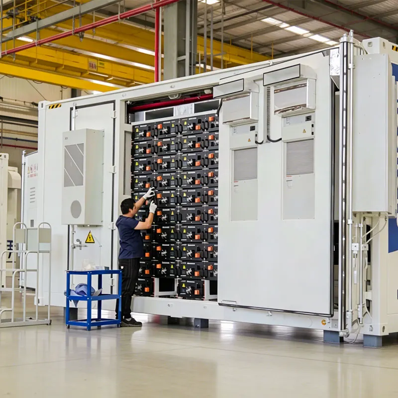
Inside a Modern High-Density 5 MWh Container
Modern products commonly combine lithium iron phosphate cells, rack-level DC protection, liquid thermal management, a multi-level BMS, gas and temperature detection, fire-response interfaces, auxiliary distribution and communications in a compact enclosure. The International Energy Agency reports in the “Technology: Battery storage” section of Global Energy Review 2026 that LFP represented around 90% of battery-storage deployments in 2025. The same section notes that most projects still cluster around two hours while more systems are reaching four hours or longer. These are global deployment observations, not a specification for every European project. See the IEA battery storage analysis.
Energy density creates engineering trade-offs
Putting more energy into one container can reduce container count, internal cabling and land per MWh. It also concentrates heat, weight and fault impact. “Liquid cooled” is therefore not a sufficient technical response. Buyers should request the allowable ambient range, temperature-derating curves, maximum cell-temperature spread under the reference duty cycle, coolant redundancy, leak detection, auxiliary demand and safe response to a cooling failure.
The control interfaces deserve the same attention. The BMS should protect cells and racks and publish current operating limits. The PCS should convert power and execute active and reactive commands. The EMS should schedule the asset according to the operating strategy. A plant controller may regulate the complete project at the PCC. If the optimiser requests discharge while the plant controller caps export and the BMS reduces available power because of temperature, the design must state which command has priority. A signal list, state machine and cause-and-effect matrix are more valuable than a brochure that says the platform is “intelligent.”
A real 5 MWh product example—and what it does not include
The site’s 5MWh liquid-cooled battery storage container is a useful example of how to read a product page. The published page identifies a 5.015 MWh nominal DC system using 314 Ah LFP cells, a 1,331 Vdc nominal bus, a stated 1,165–1,498 Vdc operating range, active liquid cooling and a 0.5C charge/discharge rate. It also lists a 45-tonne system weight and states that this is a pure DC battery container that excludes the PCS and transformer. These are vendor-published product values, not universal values for every 5 MWh design.
| Published item | Vendor-page value | Engineering implication | What the buyer must still obtain |
|---|---|---|---|
| Nominal energy | 5.015 MWh DC | Not the same as usable energy delivered at the PCC | Guaranteed usable DC and AC energy at BOL and EOL |
| DC voltage | 1,331 Vdc nominal; 1,165–1,498 Vdc range | The PCS must operate across the battery’s actual voltage envelope | Matched PCS window, current limits and cable/protection design |
| Rate capability | 0.5C stated | Suggests roughly a two-hour nominal rate, subject to conditions | Continuous-power curve versus SOC, temperature and ageing |
| Commercial boundary | DC container; PCS and transformer excluded | The product is not a complete grid-connected project | PCS, MV package, plant controller, EPC and grid-study scope |
| Weight | 45 tonnes stated | Transport, crane and foundation design become early constraints | Signed GA drawing, lifting plan and foundation reactions |
Use the page for preliminary configuration, then request the current signed datasheet, general-arrangement drawing, derating curves, auxiliary-load schedule, warranty and project-specific compliance evidence. The public page contains wording that should also be reconciled against the signed drawing before logistics are frozen. That verification step protects the EPC from designing foundations, access and DC interfaces around marketing-page information that may not be the final project release.
How to Select Power and Duration
The service should determine the MW rating—not the availability of a standard PCS. Frequency services, peak shaving, solar shifting and backup impose different response times, reserve levels and energy throughput. A buyer who starts with “we need a 5 MWh container” may discover that the dispatch profile calls for a smaller energy system with higher power, or a larger system that maintains the required output at end of life.
| Illustrative ratio | Potential decision direction | Key design check | Buyer benefit |
|---|---|---|---|
| 5 MW / 5 MWh | Short, power-intensive operation | Cell C-rate, PCS rating, thermal limits and warranty | Higher instantaneous output from the energy block |
| 2.5 MW / 5 MWh | Two-hour shifting or combined grid services | SOC competition between stacked services | Balanced power and duration for many project concepts |
| 1.25 MW / 5 MWh | Four-hour energy shifting | Charge window, market duration and PCS compatibility | More duration per MW of conversion equipment |
Engineering note: these ratios illustrate the difference between MW and MWh. They do not establish that every 5 MWh product can operate at each rating. Confirm the continuous charge and discharge limits, DC voltage range, PCS capability, thermal envelope and warranty with the selected supplier.
A 5 MWh energy waterfall: nominal capacity is not delivered capacity
The following calculation is an engineering illustration, not a performance claim for a particular product. Assume 5.000 MWh nominal DC energy, a 90% usable SOC window, 92% one-way discharge-path efficiency to the PCC and 80% retained battery capacity at the contractual end-of-life point. Fixed auxiliary consumption is not yet deducted, so it must be added from the supplier’s load schedule.
| Calculation step | Formula | Result | What it tells the buyer |
|---|---|---|---|
| Nominal DC energy | Nameplate assumption | 5.000 MWh | The brochure starting point |
| Usable DC at BOL | 5.000 × 0.90 | 4.500 MWh | Energy inside the assumed operating SOC window |
| Delivered at PCC at BOL | 4.500 × 0.92 | 4.140 MWh | Before separately modelled fixed auxiliary energy |
| Delivered at PCC at EOL | 5.000 × 0.80 × 0.90 × 0.92 | 3.312 MWh | Why a BOL nameplate cannot support an EOL guarantee by itself |
At 2.5 MW net export, the illustrative 4.140 MWh BOL output supports about 1.66 hours, not two hours. At the assumed EOL point, 3.312 MWh supports about 1.32 hours. Conversely, guaranteeing 2.5 MW for two hours at that EOL boundary requires 5.000 MWh at the PCC. Before auxiliaries, the corresponding nominal capacity would be:
Required nominal DC energy = 5.000 ÷ (0.90 × 0.92 × 0.80) = 7.55 MWh
This does not mean every two-hour project must install 7.55 MWh. It shows the consequence of the stated guarantee and assumptions. A project may instead accept declining duration, use a different SOC window, specify another efficiency boundary or plan augmentation.
| Net discharge power | Runtime from 4.140 MWh BOL | Practical interpretation |
|---|---|---|
| 1.00 MW | 4.14 hours | Longer energy-shifting window |
| 1.25 MW | 3.31 hours | Below the four-hour nameplate ratio |
| 2.00 MW | 2.07 hours | Close to a two-hour service before fixed auxiliaries |
| 2.50 MW | 1.66 hours | A nominal 2-hour ratio is not a 2-hour PCC guarantee |
| 5.00 MW | 0.83 hours | Also requires the battery and PCS to support this power |
Do not substitute round-trip efficiency for the one-way discharge efficiency used above; they answer different questions. Obtain supplier-guaranteed values at defined temperature, SOC, C-rate and ageing conditions, then add measured or guaranteed auxiliary demand. Use the site’s BESS sizing guide to prepare the load and operating inputs before requesting a configuration.
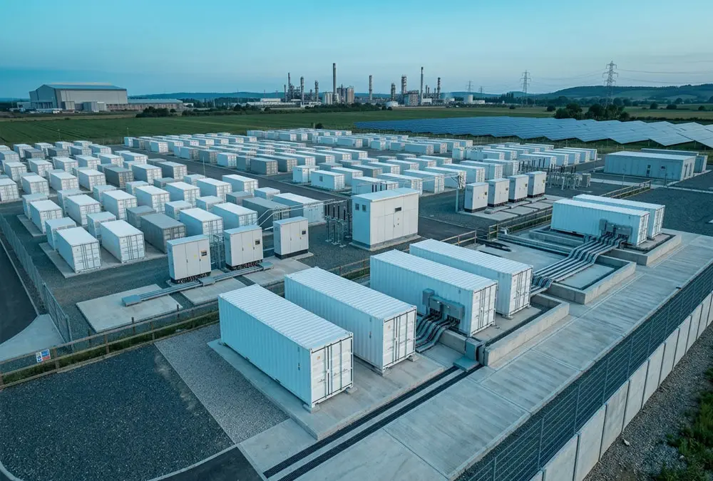
Applications Where a 5 MWh Block Can Create Value
Solar and wind shifting: storage can absorb energy that would otherwise be exported at a low value or curtailed and release it during a higher-value window. The model must use the renewable-generation profile, connection limit, charging constraints and dispatch price—not renewable nameplate capacity alone.
Energy arbitrage and grid services: a grid-connected asset can respond to wholesale prices or ancillary-service instructions, subject to national market access. The technical ability to stack services does not prove commercial compatibility. Two services may compete for the same SOC, power headroom or warranty throughput.
Industrial peak shaving: the required MW is the load above the chosen import ceiling, while the MWh is the area under that excess-load curve. Monthly electricity bills usually hide the shape and duration of peaks, so interval data is essential. A five-megawatt-hour asset purchased from monthly totals alone may be over-sized in energy yet under-sized in power.
Microgrids and resilience: backup is not simply another dispatch mode. The design must define critical loads, transfer conditions, reserve SOC, restart sequence and required autonomy. Island operation and black start require suitable controls and grid-forming capability; they should never be assumed from a standard grid-following PCS specification.
High-power EV charging: storage may buffer the difference between charger demand and a constrained grid connection. Its value depends on vehicle-arrival patterns, simultaneous charging, grid-recharge time and demand tariffs. This is a valid application, but it does not turn every charging depot into a 5 MWh use case.
European Grid Connection and Compliance
Europe is not one approval market. EU legislation and international or European standards provide a common layer, but they do not produce one universal BESS permit or one connection checklist. Grid rules, operational-notification documents, planning, fire review and environmental conditions are implemented through national, network-operator and local-authority processes. The United Kingdom must be treated separately from the EU-27 because it has its own connection and planning framework.
A country comparison for early-stage screening
The table below is a pre-FEED screening aid, not a legal opinion or substitute for the current DSO/TSO connection offer. It shows why a German technical file cannot simply be renamed for a British, Dutch, Italian or Spanish project.
| Market | Connection route or technical focus | Safety/planning distinction | 5 MWh buyer action |
|---|---|---|---|
| EU baseline | EU law and applicable EN/IEC standards sit above national connection rules; they do not issue the site’s grid approval. | Article 12 and Annex V of Regulation (EU) 2023/1542 address stationary BESS safety evidence. | Build an EU conformity file, then add the country, network and local-authority layers. |
| Germany | VDE FNN publishes voltage-level-specific Technical Connection Rules for storage. The applicable route therefore depends on the actual connection voltage and network operator. | Connection compliance does not replace permitting, fire strategy or site-specific approval. | Freeze import/export MW, voltage, protection, reactive-power capability and simulation/model requirements with the responsible operator. See VDE FNN’s storage connection overview. |
| Great Britain | ENA Engineering Recommendation G99 includes electricity storage when exporting; the DNO evaluates the connection and any export limitation. | HSE distinguishes health-and-safety duties from planning, which sits with the relevant planning authority in England, Scotland or Wales. HSE also identifies a fire-service notification duty where a site holds 25 tonnes or more of dangerous substances. | Treat import and export as separate network cases, agree G99/G100 applicability with the DNO and begin planning/fire engagement using verified battery inventory. See the ENA storage connection page and HSE’s BESS guidance. |
| Netherlands | Netbeheer Nederland’s ESM compliance procedure classifies storage modules and calls for technical data, test reports and simulation models; its version 2.0 adds on-site testing for ESM at 5 MW and above. | PGS 37-1 uses a risk-based approach for lithium energy-storage systems above 20 kWh and links scenarios, objectives and measures. | Do not confuse 5 MWh energy with the 5 MW test threshold. Confirm ESM type, preliminary/final documentation, modelling and PGS applicability. See the ESM compliance document and PGS 37-1. |
| Italy | Terna states that national transmission-grid connection is regulated through ARERA resolutions incorporated into the Terna Grid Code. Distribution-connected projects follow the relevant distribution route. | Market qualification or capacity-mechanism rules are separate from electrical connection and construction approval. | Identify TSO versus DSO scope early and separate grid-code compliance from the revenue-market qualification package. Review Terna’s connection and planning explanation. |
| Spain | Royal Decree 1183/2020 governs access and connection to transmission and distribution networks and expressly addresses storage in the application/guarantee framework. | Securing network access does not itself complete environmental, construction or municipal approval. | Define requested import and export capacity, project identity and milestone risk before lodging guarantees. Check the current consolidated text of Royal Decree 1183/2020, because it has been amended since publication. |
The practical pain point is schedule risk: buyers often request equipment quotations before the connection boundary, import/export limits and evidence route are known. The supplier then prices a standard PCS and controller, while the eventual operator requests different reactive-power capability, protection, communication or validated models. The solution is to issue a country-specific compliance matrix during concept design. It should assign every connection study, certificate, simulation model, protection setting, witness test and submission to the owner, EPC, PCS supplier or battery supplier. The site’s BESS grid connection guide provides a practical companion checklist.
Safety evidence must match the installed system
Article 12 of Regulation (EU) 2023/1542 requires stationary battery energy storage systems placed on the market or put into service to be safe during normal operation and use. Its paragraph 2 links the technical documentation to successful testing of applicable Annex V safety parameters, assessment of additional hazards and evidence that those hazards have been mitigated. Read Article 12 and Annex V in the official consolidated EU Batteries Regulation.
IEC 62933-5-2:2025 applies to electrochemical grid-integrated storage across the BESS lifecycle and addresses system-level hazards created by interactions between subsystems. That scope matters because a cell, module or rack test alone does not prove that the proposed ventilation, container spacing, electrical isolation and emergency response are adequate for the site. See the official scope of IEC 62933-5-2:2025.
For procurement, create a safety evidence matrix linking each hazard to the applicable rule, tested arrangement, proposed installation condition, mitigation, responsible party and approval authority. This exposes a frequent gap: a supplier may present valid test evidence for one configuration while proposing different rack spacing, doors, ventilation or suppression on the project.
Prepare a meaningful preliminary enquiry: send the project country, application, required MW, duration, grid voltage, import/export limits, available footprint and target operating date. These inputs are enough to identify missing studies before a product is selected.
Site, Logistics, Noise and Auxiliary Power
High energy density can reduce the number of containers without removing the balance of plant. The layout still needs PCS and transformers where they are not container-integrated, medium-voltage switchgear, auxiliary supplies, cable routes, access roads, drainage, fencing, emergency access and space for replacement or augmentation. A compact brochure arrangement may not include local fire separation, acoustic mitigation or maintainable clearances.
Transport weight, centre of gravity, lifting points and route restrictions must be established before civil design. A heavier high-density enclosure can reduce unit count while increasing crane, foundation and delivery constraints. Ask for certified transport drawings, lifting procedures, foundation reactions and permissible transport condition—including whether batteries are shipped installed and at what SOC.
Noise and auxiliary consumption also affect project value. Liquid-cooling equipment, PCS fans and transformers can create material night-time sound at sensitive boundaries. Cooling, heating, pumps, controls, detection, lighting and security reduce net delivered energy. Require an auxiliary load schedule with normal, peak, standby and cold-start conditions, then state whether those loads are included in efficiency and capacity guarantees.
What Does a 5MWh BESS Really Cost?
There is no defensible universal price for a five-megawatt-hour project. A factory-gate DC container, an AC block delivered to site and a commissioned European MV project have different scopes. Country, duration, PCS power, grid functions, fire strategy, civil conditions, transport, tax, warranties and connection works can move the installed cost materially. A price without a date, currency, geography, energy boundary and inclusions is not a benchmark.
Use a three-axis project cost model
Installed project cost
= energy-scaled cost + power-scaled cost + site-fixed cost + lifecycle allowance
Energy-scaled costs change mainly with installed MWh: cells, modules, racks and a share of the enclosure and thermal system. Power-scaled costs change mainly with MW or MVA: PCS, transformer, switchgear and some protection equipment. Site-fixed costs include development, studies, controls integration, roads, drainage, fencing, communications and project management. Lifecycle allowances cover service, spares, degradation, augmentation and replacement obligations.
The National Renewable Energy Laboratory uses the same underlying logic in the “Capital Expenditures” methodology of its utility-scale battery storage page: total system cost is separated into a battery-pack cost multiplied by duration and a balance-of-system cost expressed per kW. NREL’s data represents a US modelling framework and should not be copied into a European budget, but the separation of energy and power costs is valuable. Review the equation and scope in the NREL Annual Technology Baseline methodology.
| Cost bucket | Primary drivers | Common omission | Evidence to request |
|---|---|---|---|
| DC battery system | MWh, chemistry, duty cycle and energy guarantee | Usable-energy and degradation boundary | Capacity test and warranty model |
| Power conversion and MV | MW/MVA, voltage, reactive power and grid functions | Temperature derating and protection studies | Capability curves and single-line diagram |
| Civil and installation | Ground, drainage, access, cable route and fire layout | Crane, abnormal transport and remediation | Quantities, exclusions and geotechnical basis |
| Grid connection | Country, network operator, voltage and compliance studies | External reinforcement and model validation | Connection offer and responsibility matrix |
| Lifecycle | Throughput, temperature, service and end-of-life target | Augmentation, auxiliaries and data access | Long-term model and service scope |
Cost sensitivity: translate unit-rate changes into project money
A bid review becomes clearer when every unit-rate difference is converted into total euros. For a nominal 5,000 kWh battery block, the general relationship is:
Installed CAPEX = (battery-side €/kWh × 5,000 kWh) + (power-side €/kW × selected kW) + fixed site/grid cost + lifecycle allowance
This is a scope-normalisation equation, not a current market-price forecast. Replace each variable with dated, location-specific supplier or contractor quotations.
| Illustrative change | Calculation | Project impact | Decision lesson |
|---|---|---|---|
| Battery-side rate changes by €10/kWh | €10 × 5,000 kWh | €50,000 | Check whether the cheaper bid uses the same usable-energy and warranty boundary. |
| Power-side rate changes by €25/kW on a 2.5 MW design | €25 × 2,500 kW | €62,500 | PCS/MV cost should be compared per kW or kVA, not hidden inside €/kWh. |
| Unexpected grid or civil cost of €100,000 | €100,000 ÷ 5,000 kWh | €20/kWh when normalised | A cheap container cannot compensate for omitted project scope. |
| Energy guarantee falls from 5.0 to 4.14 MWh at the PCC | Same price ÷ 4,140 rather than ÷ 5,000 kWh | Effective €/usable-kWh rises by about 20.8% | Normalise price to guaranteed usable PCC energy, not nominal DC nameplate. |
The last row follows directly from the illustrative energy waterfall: 5.000 ÷ 4.140 = 1.208. It does not claim that every system loses 17.2% of nameplate energy; it demonstrates why two identical total prices can have different economic value when their guarantee boundaries differ. Ask every bidder to submit both total project price and normalised cost per guaranteed usable kWh at the PCC, at BOL and at the agreed EOL date.
The practical comparison metric is therefore not the lowest container €/kWh. It is the cost of meeting the required service at the agreed boundary and date. Normalise quotations to the same usable energy, MW, PCC, delivery location, Incoterms, commissioning scope, warranty duty cycle and end-of-life obligation before comparing them.
Europe Versus the United States
A global product platform can support projects in multiple markets, but the approval evidence is not interchangeable. European projects typically combine EU legislation, IEC or adopted EN standards, national grid rules and local planning or fire requirements. US projects commonly work through UL standards, NFPA 855, the International Fire Code, local authorities having jurisdiction and the relevant interconnection process.
UL Solutions describes UL 9540A as the American and Canadian national test method for evaluating thermal-runaway fire propagation in energy storage systems. Its page explains cell, module, unit and installation-level test purposes and the relationship to NFPA 855 and building/fire codes. That evidence is important for US projects and may inform international due diligence, but it should not be presented as a universal European legal requirement. See the official UL 9540A test-method explanation.
Degradation, Warranty and Augmentation
A 5 MWh beginning-of-life rating does not answer what the owner will receive in year ten or fifteen. The project must choose among three strategies: install excess capacity at commercial operation, accept declining usable energy, or add battery capacity later. Each changes the upfront cost, footprint, inverter loading and warranty structure.
Service stacking creates another hidden conflict. The EMS may be technically capable of combining arbitrage, peak shaving and ancillary services, but the warranty may limit annual throughput, equivalent full cycles, SOC range, C-rate or temperature exposure. If the financial model assumes more work than the warranty permits, the owner carries the gap. Connect the optimiser’s dispatch rules to a degradation model and a contractual throughput budget.
Augmentation is not simply “buying more batteries later.” The design must reserve land, DC or AC capacity, protection, communication addresses and maintenance access. It must also address mixing battery ages, future product compatibility and responsibility for recommissioning. Total cost of ownership should include these items alongside efficiency losses, auxiliary energy, spares, service and availability—not only the initial equipment price.
How to Compare Supplier Proposals
Issue a common bid schedule rather than accepting each supplier’s preferred headline metrics. Require nominal DC energy, usable DC energy, usable AC energy, continuous MW, overload capability, SOC window, temperature derating, auxiliary load, beginning- and end-of-life values, efficiency boundary, availability definition and annual throughput. The commercial schedule should also state delivery terms, commissioning scope, taxes, spares, service and exclusions.
Red flags include a 5 MWh claim with no measurement boundary, cycle-life figures without DoD and temperature, efficiency without auxiliary treatment, a cell certificate presented as complete system approval, or an EPC price without connection and civil exclusions. Supplier evaluation should extend to bankability, factory capacity, reference-system similarity, European service coverage, data access and replacement strategy. The site’s BESS EPC contractor selection guide provides a complementary procurement checklist.
FAT, SAT and Performance Acceptance
Factory acceptance testing should verify the functions that can be demonstrated before shipment: BMS and PCS control, alarm and trip logic, cooling response, communication, time synchronisation, data recording, cybersecurity configuration and safe operating states. The FAT record should identify software and firmware versions so that the site system can be checked against the tested baseline.
Site acceptance testing should confirm installed wiring, protection, metering, emergency stops, communications, active and reactive power, export limitation and interaction with the network operator or optimiser. Performance testing should then verify usable energy, efficiency, response and other guarantees at the contractual boundary.
A strong guarantee can become unenforceable if the test method is written after construction. Define the initial SOC, power profile, ambient conditions, meter class, sampling interval, auxiliary treatment, allowable interruptions, calculation method and retest rights during procurement. CIGRE Technical Brochure 869 lists component, site acceptance, SCADA, system, failure-mode, grid-connection and performance tests in Chapter 4 of its published contents, providing a useful lifecycle checklist. See the CIGRE TB 869 summary and contents.
The 5MWh Project Fit Gate
Before approving a product or budget, pass the project through five decision gates:
- Service gate: Is the duty cycle based on real load, generation or market data?
- Power-duration gate: Do the required MW, MWh, response and reserve work together?
- Boundary gate: Is every capacity, efficiency and cost value tied to DC, AC or PCC?
- Site-compliance gate: Can the arrangement be transported, installed, connected, maintained and approved in the actual jurisdiction?
- Evidence gate: Can the supplier prove the requirement through design documents, tests and contractual acceptance?
A project that fails a gate is not necessarily unviable. It is simply not ready for a fixed equipment commitment. Resolving the missing input before purchase is usually cheaper than redesigning after delivery.
Frequently Asked Questions
How many MW is a 5MWh BESS?
MWh does not determine MW. Conceptually, 5 MWh could be paired with 5 MW for one hour, 2.5 MW for two hours or 1.25 MW for four hours. Actual output depends on the battery, PCS, temperature, SOC and warranty limits.
Does a 5 MWh container deliver 5 MWh to the grid?
Not automatically. A 5 MWh figure may be nominal DC energy. Usable SOC limits, PCS and transformer losses, auxiliary consumption, temperature and degradation can reduce net energy at the PCC.
Is a 5 MWh battery suitable for an industrial site?
It may be suitable for a large industrial load, solar shifting, resilience or peak control, but the answer requires interval load data, tariff and outage objectives, connection limits, available charging energy, site constraints and an operating profile.
What information is needed for a reliable price?
At minimum: project country, application, required MW and duration, energy boundary, grid voltage, import/export limits, duty cycle, end-of-life target, available footprint, environmental conditions, delivery scope, compliance requirements and target date.
Conclusion: Specify the Project Before Buying the Block
The right 5MWh BESS is not necessarily the container with the highest cell density or lowest factory-gate €/kWh. It is the configuration that delivers the required MW and net energy at the agreed boundary, complies with the actual connection and safety route, fits the site, and can be verified through commissioning and performance testing.
For European projects, keep EU law, IEC or EN standards, national grid rules and local approvals distinct. For US projects, apply the appropriate UL, NFPA, interconnection and AHJ route instead of importing European assumptions. In every market, compare offers on a common scope and model lifecycle obligations before treating an equipment price as a project cost.
Request a 5MWh BESS Sizing and Project Configuration Review
Share your project country, operating objective, MW requirement, duration, grid voltage, connection limits and available site area. The review can identify the appropriate system boundary, missing studies and the information required for a comparable technical proposal.
 https://anengjipower.com/wp-content/uploads/2026/06/epc-vs-turnkey-solar-project-bess.webp
675
1000
Charging Station Engineer
https://anengjipower.com/wp-content/uploads/2025/09/anengji-dc-fast-charging-station-manufacturer-and-supplier-logo-white-1.png
Charging Station Engineer2026-06-22 07:16:042026-06-24 07:13:17What Is the Difference Between EPC and Turnkey Contract Models in Energy Projects?
https://anengjipower.com/wp-content/uploads/2026/06/epc-vs-turnkey-solar-project-bess.webp
675
1000
Charging Station Engineer
https://anengjipower.com/wp-content/uploads/2025/09/anengji-dc-fast-charging-station-manufacturer-and-supplier-logo-white-1.png
Charging Station Engineer2026-06-22 07:16:042026-06-24 07:13:17What Is the Difference Between EPC and Turnkey Contract Models in Energy Projects? https://anengjipower.com/wp-content/uploads/2026/06/anengji-commercial-solar-plus-storage-benefits-site.webp
675
1000
Charging Station Engineer
https://anengjipower.com/wp-content/uploads/2025/09/anengji-dc-fast-charging-station-manufacturer-and-supplier-logo-white-1.png
Charging Station Engineer2026-06-20 14:34:102026-06-20 14:37:43What Are the Top Benefits of Solar Battery Storage in Factories?
https://anengjipower.com/wp-content/uploads/2026/06/anengji-commercial-solar-plus-storage-benefits-site.webp
675
1000
Charging Station Engineer
https://anengjipower.com/wp-content/uploads/2025/09/anengji-dc-fast-charging-station-manufacturer-and-supplier-logo-white-1.png
Charging Station Engineer2026-06-20 14:34:102026-06-20 14:37:43What Are the Top Benefits of Solar Battery Storage in Factories? https://anengjipower.com/wp-content/uploads/2026/06/modular-commercial-solar-battery-storage-cabinet.webp
675
1000
Charging Station Engineer
https://anengjipower.com/wp-content/uploads/2025/09/anengji-dc-fast-charging-station-manufacturer-and-supplier-logo-white-1.png
Charging Station Engineer2026-06-18 09:16:522026-07-03 03:05:13What Is Solar Battery Storage? Complete C&I Engineering Guide
https://anengjipower.com/wp-content/uploads/2026/06/modular-commercial-solar-battery-storage-cabinet.webp
675
1000
Charging Station Engineer
https://anengjipower.com/wp-content/uploads/2025/09/anengji-dc-fast-charging-station-manufacturer-and-supplier-logo-white-1.png
Charging Station Engineer2026-06-18 09:16:522026-07-03 03:05:13What Is Solar Battery Storage? Complete C&I Engineering Guide

Leave a Reply
Want to join the discussion?Feel free to contribute!