
Introduction
Europe’s storage market has moved from early adoption to delivery at scale. SolarPower Europe’s European Battery Market Outlook 2026–2030 reports that Europe installed 36 GWh of battery storage in 2025—48% more than in 2024—taking operational capacity above 100 GWh. It also records a structural change: utility-scale systems supplied more than half of annual deployment for the first time. See Figure 1 and the market overview in the SolarPower Europe outlook.
That growth does not make projects easier to design. It makes weak assumptions more expensive. A developer can secure land and equipment yet discover that import capacity is insufficient. An EPC can compare two identical-looking MW/MWh offers that use different SOC windows and performance boundaries. A C&I buyer can pay for energy capacity that sits idle because the PCS, transformer, tariff window, or control strategy was never matched to the site. These are not minor optimisation gaps: they can delay connection, weaken the business case, or turn a low-price bid into a costly variation order.
A reliable battery energy storage system design therefore does not begin with a catalogue, a container size, or a supplier’s headline MWh figure. It begins with a defined operating problem: what the system must do, when it must do it, at which electrical boundary performance will be measured, and which national grid, safety, planning, and commercial rules apply.
What you will be able to decide after reading:
- Which load, market, grid, and site data must be fixed before requesting quotations
- How to separate MW, MWh, duration, usable energy, losses, and degradation
- How to select architecture and assign battery, PCS, BMS, EMS, and plant-control responsibilities
- Which evidence belongs in procurement, FAT, SAT, commissioning, and performance acceptance
This guide is written for European storage developers, EPC engineers, system integrators, and owner-side technical evaluators preparing a conceptual design, front-end engineering design (FEED), or procurement specification. It also helps commercial and industrial energy buyers understand why two proposals with the same MW and MWh can produce very different availability, operating cost, permitting risk, and lifetime value.
The central design principle: every requirement should form a traceable chain from operating objective to model input, equipment function, verification method, and contractual acceptance criterion. If one link is missing, the project may look complete on a single-line diagram while remaining difficult to permit, commission, or operate profitably.
What Does BESS Design Actually Include?
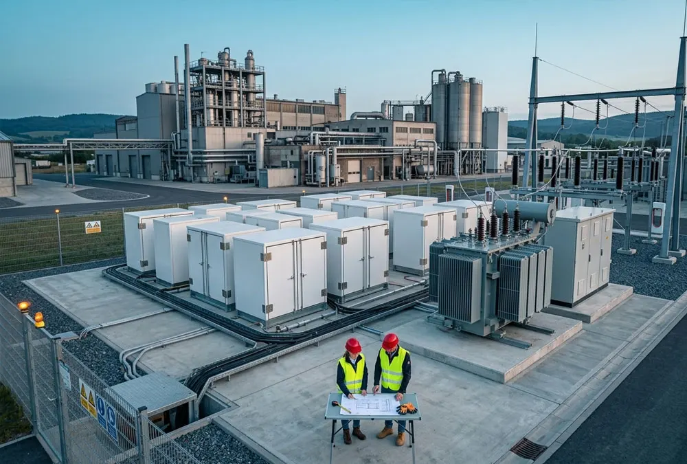
Battery energy storage system design spans more than the battery enclosure. A project-level BESS includes cells, modules, racks, DC collection, battery management systems (BMS), power conversion systems (PCS), transformers, switchgear, protection, auxiliary supplies, thermal management, fire-risk controls, an energy management system (EMS), a plant controller, communications, metering, civil works, and the point of connection (PCC). Each interface can affect safety, efficiency, availability, and warranty compliance.
The work also changes by project stage. Conceptual design establishes feasibility and an initial power/energy range. FEED fixes the principal architecture, site layout, grid boundary, equipment blocks, major risks, and cost basis. Detailed design completes cable sizing, protection coordination, earthing, civil details, control logic, construction drawings, and test procedures. Treating a conceptual vendor layout as a construction-ready design is a common source of change orders.
The Five-Boundary BESS Design Framework
| Boundary | Question to settle | Buyer benefit |
|---|---|---|
| Operational | What duty cycle, service, response time, and reserve state of charge must the asset deliver? | Prevents sizing a battery for the wrong job. |
| Electrical | Are power, energy, efficiency, and losses defined at DC, PCS AC, transformer, or PCC? | Makes supplier guarantees comparable. |
| Control | Which controller owns dispatch, protection, export limitation, and failure response? | Reduces integration and commissioning disputes. |
| Compliance | Which EU, national, DSO/TSO, planning, fire, and insurer requirements apply? | Limits redesign and approval delay. |
| Contractual | How are capacity, efficiency, availability, degradation, and augmentation accepted? | Connects engineering evidence to commercial remedies. |
1. Start with the Application and Duty Cycle
The design basis should name the service before it names the battery. Peak shaving, PV self-consumption, energy arbitrage, backup, congestion management, and frequency services create different power profiles, cycle depths, response requirements, resting periods, and reserve-SOC constraints. A system that performs one full discharge each evening is not exposed to the same operating stress as a system following a rapidly changing grid signal.
A peer-reviewed Technical University of Munich study on standard BESS profiles identifies full-equivalent cycles, efficiency, depth of cycles, resting periods, changes of power direction, and energy throughput between direction changes as characteristics that distinguish storage applications. The study’s methodology section transforms source profiles into battery power and SOC profiles before evaluating design and operation. That supports an important procurement rule: issue a reference duty cycle to bidders instead of asking them to interpret a vague use case. See the Technical University of Munich publication.
Without that reference profile, two vendors can quote the same 2 MW/4 MWh label while assuming different SOC windows, cycle counts, temperature limits, or degradation allowances. The apparent price comparison is then false. Resolve the problem by specifying at least the charge and discharge schedule, required response time, expected annual throughput, minimum reserve, operating temperature, and whether services may be stacked.
2. Collect the Data Required Before Sizing
Sizing quality cannot exceed input-data quality. Monthly electricity bills may reveal consumption and demand charges, but they usually cannot show the duration, coincidence, and recurrence of short peaks. For a C&I project, use interval load data at a resolution appropriate to the control objective, together with PV generation, tariffs, critical loads, grid limits, and operating schedules. Grid-service projects need the relevant signal or a representative profile, not a generic daily cycle.
| Input | Design use | Risk if missing |
|---|---|---|
| Interval load and PV data | Power, energy, charge availability, export modelling | Oversizing or failure to control actual peaks |
| Import/export limits and connection voltage | PCS, transformer, protection, dispatch constraints | Non-compliant or stranded capacity |
| Site and environmental data | Layout, cooling, noise, drainage, access | Late civil redesign or derating |
| Commercial and warranty horizon | Lifecycle model, augmentation, acceptance dates | An attractive year-one model with weak lifetime value |
In a German industrial feasibility example, the engineering scope included application prioritisation, regulatory and technical conditions, site space, grid capacity, energy-flow simulation, investment cost, and supply-continuity value. That is a useful reminder that preliminary sizing is a scenario exercise, not a single spreadsheet cell. The example is documented by INP International Projects; it is a project reference, not a universal design standard.
3. Size Power and Energy Separately
Power, expressed in kW or MW, determines how fast the system can charge or discharge. Energy, expressed in kWh or MWh, determines how long that power can be sustained. A 2 MW/4 MWh system has a nominal two-hour ratio, but it does not automatically deliver 2 MW at the PCC for two hours. The result depends on usable SOC, power limits across SOC and temperature, conversion losses, auxiliary consumption, and the measurement boundary.
A transparent sizing equation
Required nominal battery energy
= required delivered energy ÷ usable SOC window ÷ discharge-path efficiency × degradation allowance × availability or redundancy allowance
This is a design structure, not a source of universal default values. SOC window, efficiency, degradation, and availability are condition-dependent and must be tied to a duty cycle, temperature range, system boundary, warranty, and project date. For example, an owner requiring guaranteed usable energy at the PCC at year ten needs a different nominal capacity from an owner accepting a lower end-of-life capacity or planned augmentation.
A frequent buyer problem appears when gross DC energy is compared with net AC energy. One proposal may quote installed cell energy while another quotes usable energy after SOC limits; neither may include HVAC or transformer losses. The solution is a bid form with common boundaries: gross DC energy, usable DC energy, PCS AC energy, PCC energy, auxiliary consumption, and the exact test conditions for each.
4. Choose the System Architecture
Architecture should follow the operating objective and existing electrical system. In a new solar-plus-storage project, DC coupling may recover clipped PV energy and reduce some conversion duplication, but it creates shared controls and a charging-path dependency. AC coupling is often easier to retrofit and can give the battery an independent grid connection path, but it introduces its own conversion and protection arrangement. Neither option is inherently superior.
The same reasoning applies to central versus distributed PCS blocks. A large central block may simplify equipment count, while smaller blocks can improve fault isolation and partial availability. Yet excessive fragmentation adds transformers, switchgear, controls, cable, protection, and maintenance interfaces. Evaluate architecture through failure impact, maintainability, grid-code functions, expansion, cable losses, land use, and total installed cost—not PCS efficiency alone.
At this stage, produce a block diagram and preliminary single-line diagram showing the cell-to-PCC chain. Explicitly identify the battery limit, PCS limit, balance-of-plant scope, auxiliary source, revenue meter, protection ownership, and communications gateway. These boundaries later become contract interfaces.
5. Integrate the Battery, PCS, BMS, EMS and Plant Controller
A BESS is a coordinated control system. The BMS protects cells and racks, estimates SOC and state of health, manages balancing, and communicates operating limits. The PCS converts power and implements active/reactive power commands within its electrical and thermal capability. The EMS schedules energy according to business rules. A plant controller may regulate the complete facility at the PCC, particularly where PV, loads, generators, or multiple PCS blocks share one connection.
Problems emerge when all suppliers claim to “control the system” but no document defines command priority. What happens when the optimiser requests discharge, the plant controller must cap export, and the BMS reduces available power because of temperature? The project needs a control hierarchy, signal list, interface responsibility matrix, state machine, alarm philosophy, and cause-and-effect matrix. Communication loss must have an agreed safe state; it should not be discovered during SAT.
Data requirements belong in the design as well. Specify time resolution, retention, API access, meter accuracy, timestamp synchronisation, user roles, remote access, patch responsibility, and ownership of raw and processed data. Without these provisions, an owner may be unable to verify efficiency, availability, or warranty conditions after handover.
6. Design for the Actual European Grid Connection
There is no single connection checklist that makes a BESS compliant across Europe. EU law and European network frameworks influence national systems, but detailed requirements depend on the country, voltage level, connection agreement, and relevant DSO or TSO. The United Kingdom must also be treated separately from EU-27 requirements.
Germany illustrates why early confirmation matters. VDE FNN states in its section “Bundesweite Netzanschlussregeln für Speicher” that technical connection and operating requirements are defined through voltage-level-specific Technical Connection Rules, supplemented by guidance for low-voltage storage. Its “Zielgruppen und Nutzen” section also identifies buyers, installers, grid operators, and manufacturers as separate users of the connection framework. Review the VDE FNN storage connection guidance.
Do not assume that obtaining a physical connection automatically settles operational capacity in both directions. A battery is both load and source, so the design team should confirm import capacity, export capacity, metering, protection, reactive-power requirements, operating envelopes, and any flexible connection conditions. In its storage FAQ under “Wie erfolgt die Bestellung der Netzanschlusskapazität bei Speichern?”, Germany’s Federal Network Agency explains that storage must reserve connection capacity for both withdrawal and feed-in because of this dual role. This makes import and export limits a formal battery energy storage system design input, not an issue to defer until commissioning. See the Bundesnetzagentur storage FAQ.
US comparison: projects in the United States commonly reference IEEE 1547/1547.9 for DER interconnection and UL 9540, UL 9540A, and NFPA 855 in the safety and installation framework. These are useful for US projects and global supplier discussions, but they do not replace European or national requirements.
7. Resolve Site, Civil, Thermal and Auxiliary-Power Constraints
A technically attractive battery cannot be installed where emergency access, maintenance clearances, drainage, flood level, noise, cable routes, or fire-risk controls are unacceptable. Complete a layout feasibility review before freezing the equipment block. Include containers or cabinets, PCS, transformers, switchgear, auxiliary equipment, fencing, access roads, turning space, cable trenches, foundations, drainage, and future augmentation zones.
Auxiliary power deserves its own load schedule. Cooling, heating, ventilation, pumps, controls, fire systems, lighting, security, and communications affect both electrical design and net performance. Concurrent motor starting can create a higher peak than average auxiliary consumption. Cold climates may shift the design problem from cooling to heating, while hot conditions may reduce available battery or PCS power.
If auxiliaries are omitted from the financial and performance model, the owner may buy a system that meets a gross equipment rating but misses net PCC output. Define whether efficiency and energy guarantees include auxiliary consumption, and ensure the auxiliary supply remains available in every required operating and shutdown state.
8. Build European Safety and Battery Compliance into the Design
Safety evidence should shape the layout and control philosophy, not be assembled after equipment selection. Regulation (EU) 2023/1542 defines a stationary battery energy storage system as an industrial battery designed to store and deliver electrical energy to the grid or end users. Article 12, “Safety of stationary battery energy storage systems,” requires systems placed on the market or put into service to be safe during normal operation and use. It also connects technical documentation to testing of the safety parameters in Annex V, assessment of additional hazards, mitigation evidence, and instructions for hazards such as fire or explosion. Consult the official EU Batteries Regulation and confirm its current consolidated version for the project date.
At the international-standard level, the scope statement of IEC 62933-5-1:2024 covers hazard identification, risk assessment, and risk mitigation for grid-integrated electrical energy storage systems. IEC’s description notes actionable criteria in Clauses 6 and 7 and expanded test criteria in Clause 8. The updated IEC 62933-5-2:2025 addresses electrochemical grid-integrated systems across the BESS lifecycle and focuses on hazards created by subsystem interactions.
These references do not create one universal European fire-approval route. Applicable EN adoptions, national building and fire rules, local planning conditions, fire-service expectations, and insurer requirements must be checked for the project jurisdiction. A supplier test report is not automatically evidence that every proposed layout is acceptable. Compare the tested arrangement with the real installation: enclosure type, module configuration, spacing, walls, ventilation, detection, explosion controls, and suppression strategy.
9. Define Performance, Degradation and Warranty Boundaries
Performance guarantees are useful only when the test boundary and operating conditions are explicit. A round-trip-efficiency figure measured across a battery DC boundary cannot be compared directly with a PCC guarantee that includes PCS, transformer, cable, controls, and auxiliaries. Likewise, “availability” can mean equipment uptime, dispatch availability, or compliance with requested output after exclusions.
| Guarantee | Define before contract | Buyer consequence |
|---|---|---|
| Usable energy | Boundary, SOC range, power, temperature, test date | Confirms deliverable duration rather than installed cell energy |
| Efficiency | Charge/discharge points, auxiliaries, profile, SOC endpoints | Protects the revenue and energy-cost model |
| Availability | Dispatch definition, exclusions, partial derating, data source | Makes lost-service remedies enforceable |
| Degradation | Duty cycle, throughput, temperature, calendar time, augmentation | Aligns warranty with actual operation |
Decide early whether the owner will install extra capacity at commercial operation, accept declining usable energy, or add modules later. Augmentation introduces land, electrical, control, warranty, and mixed-age-battery issues. It is a lifecycle design decision, not merely a future purchasing option.
10. Convert the Design into Procurement Deliverables
A strong specification tells bidders what must be achieved and how evidence will be evaluated. It should not prescribe unnecessary proprietary details, but it must close the interfaces that affect safety, compliance, and performance.
- Design basis and reference duty cycle
- Power, energy, degradation, and auxiliary-load calculations
- Single-line diagram, general arrangement, and equipment schedules
- Protection philosophy, earthing study, and cable calculations
- Control architecture, interface matrix, signal list, and cause-and-effect matrix
- Safety assessment, applicable test evidence, and emergency response inputs
- Grid-compliance evidence and modelling responsibilities
- FAT, SAT, commissioning, and performance-test procedures
- O&M, spares, cybersecurity, data access, and augmentation plan
CIGRE Technical Brochure 869 provides a useful lifecycle reference. Its published table of contents separates technical requirements, substation design, installation and commissioning, maintenance, and end of life. Chapter 4 specifically lists component, site acceptance, SCADA, system, failure-mode, grid-connection, and performance testing. Review the official CIGRE brochure summary and contents.
Need a practical starting point? Prepare your project country, load or dispatch profile, grid import/export limits, required duration, available footprint, and operating objective. These inputs allow a preliminary design-basis review before equipment is selected.
11. Verify the System through FAT, SAT and Commissioning
Testing should prove the requirements established in the design basis. FAT can verify BMS and PCS functions, communications, alarm and trip logic, controller states, cybersecurity configuration, and available factory-level integration. It cannot reproduce every site condition. SAT should therefore confirm installed wiring, point-to-point signals, protection, metering, emergency stops, energisation sequences, export limitation, active/reactive power, and communication with the grid operator or optimiser.
Performance testing then closes the contractual loop. Specify stabilisation, initial SOC, ambient limits, meter class, sampling interval, acceptable interruptions, auxiliary treatment, calculation method, and retest rights. Capture a baseline for usable energy, efficiency, response, and system availability so later degradation discussions have defensible evidence.
A recurring project failure is to write a strong headline guarantee but leave the test method until commissioning. By that point, the revenue meter, data historian, or operating profile may be unsuitable. Draft the performance-test procedure during procurement and review it alongside the single-line diagram and control philosophy.
European BESS Design Review Checklist
- The application, duty cycle, and service-stacking rules are defined.
- Power and energy are sized separately at stated electrical boundaries.
- Import and export capacity are confirmed with the relevant network operator.
- SOC window, losses, auxiliaries, degradation, availability, and augmentation are modelled.
- The battery, PCS, BMS, EMS, plant controller, and optimiser interfaces have named owners.
- The layout addresses access, maintenance, drainage, noise, thermal conditions, and safety evidence.
- EU requirements, relevant standards, national rules, and local approvals are kept distinct.
- Performance guarantees include measurement points, conditions, and test methods.
- FAT, SAT, commissioning, data handover, and acceptance criteria are agreed before manufacture.
Conclusion: Design the Evidence Chain, Not Just the Equipment
The best battery energy storage system design is not necessarily the one with the highest cell energy, the fewest containers, or the lowest initial equipment price. It is the design that converts a verified operating need into an installable architecture, demonstrates compliance in the actual country, defines control and supplier interfaces, and can be tested at the same boundary used by the business case.
For European projects, this requires deliberate separation of EU legislation, international or European standards, national grid rules, and local approval conditions. It also requires commercial discipline: degradation, auxiliaries, data access, availability, and commissioning cannot remain footnotes. When these issues are resolved before procurement, the buyer receives proposals that are easier to compare and a project that is easier to permit, finance, commission, and operate.
Request a BESS Sizing and Design Consultation
Share your project country, interval load or dispatch data, connection capacity, operating objective, required duration, and available site area. We can help structure a preliminary design basis, identify missing inputs, and define the next engineering study.
 https://anengjipower.com/wp-content/uploads/2026/06/epc-vs-turnkey-solar-project-bess.webp
675
1000
Charging Station Engineer
https://anengjipower.com/wp-content/uploads/2025/09/anengji-dc-fast-charging-station-manufacturer-and-supplier-logo-white-1.png
Charging Station Engineer2026-06-22 07:16:042026-06-24 07:13:17What Is the Difference Between EPC and Turnkey Contract Models in Energy Projects?
https://anengjipower.com/wp-content/uploads/2026/06/epc-vs-turnkey-solar-project-bess.webp
675
1000
Charging Station Engineer
https://anengjipower.com/wp-content/uploads/2025/09/anengji-dc-fast-charging-station-manufacturer-and-supplier-logo-white-1.png
Charging Station Engineer2026-06-22 07:16:042026-06-24 07:13:17What Is the Difference Between EPC and Turnkey Contract Models in Energy Projects? https://anengjipower.com/wp-content/uploads/2026/06/anengji-commercial-solar-plus-storage-benefits-site.webp
675
1000
Charging Station Engineer
https://anengjipower.com/wp-content/uploads/2025/09/anengji-dc-fast-charging-station-manufacturer-and-supplier-logo-white-1.png
Charging Station Engineer2026-06-20 14:34:102026-06-20 14:37:43What Are the Top Benefits of Solar Battery Storage in Factories?
https://anengjipower.com/wp-content/uploads/2026/06/anengji-commercial-solar-plus-storage-benefits-site.webp
675
1000
Charging Station Engineer
https://anengjipower.com/wp-content/uploads/2025/09/anengji-dc-fast-charging-station-manufacturer-and-supplier-logo-white-1.png
Charging Station Engineer2026-06-20 14:34:102026-06-20 14:37:43What Are the Top Benefits of Solar Battery Storage in Factories? https://anengjipower.com/wp-content/uploads/2026/06/modular-commercial-solar-battery-storage-cabinet.webp
675
1000
Charging Station Engineer
https://anengjipower.com/wp-content/uploads/2025/09/anengji-dc-fast-charging-station-manufacturer-and-supplier-logo-white-1.png
Charging Station Engineer2026-06-18 09:16:522026-07-03 03:05:13What Is Solar Battery Storage? Complete C&I Engineering Guide
https://anengjipower.com/wp-content/uploads/2026/06/modular-commercial-solar-battery-storage-cabinet.webp
675
1000
Charging Station Engineer
https://anengjipower.com/wp-content/uploads/2025/09/anengji-dc-fast-charging-station-manufacturer-and-supplier-logo-white-1.png
Charging Station Engineer2026-06-18 09:16:522026-07-03 03:05:13What Is Solar Battery Storage? Complete C&I Engineering Guide

Leave a Reply
Want to join the discussion?Feel free to contribute!