
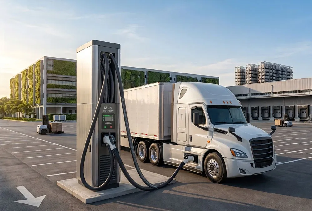
1. Understanding Heavy-Duty Truck EV Charging Architecture & System Engineering
Transitioning a commercial logistics fleet from internal combustion engine (ICE) vehicles to zero-emission battery electric trucks (BETs) represents a profound paradigm shift in energy procurement and operational workflows. Unlike light-duty passenger EV charging—which primarily relies on AC Level 2 power or modest 50kW–150kW DC plugs—commercial truck EV charging demands enterprise-grade electrical engineering capable of handling continuous mega-watt scale power throughput.
Technical Scope & Duty-Cycle Categorization
Industrial fleet electrification encompasses distinct commercial vehicle categories, each exhibiting starkly different power transfer requirements, battery pack capacities, and daily duty cycles:
- Medium-Duty Commercial Fleets (Class 4–6): Regional pickup/delivery trucks, box trucks, and municipal utility vehicles featuring battery pack sizes ranging between 150 kWh and 300 kWh. These vehicles typically operate on predictable single-shift routes and recharge overnight using 60kW to 180kW DC fast chargers.
- Heavy-Duty Commercial Trucks (Class 7–8): Long-haul freight tractors, regional haulers, and drayage rigs equipped with massive 350 kWh to 800+ kWh battery systems. Operating across multi-shift or continuous highway routes, these rigs demand ultra-fast 350kW to 600kW DC chargers or next-generation Megawatt Charging Systems (MCS) to replenish energy during mandated driver rest intervals.
- Specialized Industrial & Off-Highway Fleets: Terminal tractors (yard dogs), refuse collection trucks, mining haulers, and airport ground support equipment. These units undergo severe start-stop cycles and require ruggedized high-power charging stations engineered to withstand extreme vibrations, dust, and continuous thermal strain.
The Physics of Commercial Charging: Why Standard Infrastructure Fails
Replenishing an 800 kWh battery pack on a Class 8 electric semi-truck within a 40-minute driver rest window requires delivering roughly 900 to 1,000 kW of continuous DC power. If attempted with a standard 50kW passenger EV charger, the vehicle would occupy the bay for over 16 hours, causing severe operational bottlenecks, missed delivery windows, and unmanageable fleet downtime. High-power heavy-duty charging infrastructure relies on liquid-cooled cable technology, advanced Silicon Carbide (SiC) power switching modules, and active thermal management to deliver currents up to 500A via CCS2/CCS1 connectors or up to 3,000A via MCS interfaces without exceeding safety temperature thresholds.
Global Market Outlook & Regulatory Imperative:
Global commercial vehicle electrification is expanding exponentially due to strict zero-emission vehicle (ZEV) mandates, such as California’s Advanced Clean Fleets (ACF) regulation and Europe’s heavy-duty CO2 reduction targets. According to industry reports, global electric heavy truck sales surpassed 230,000 units, representing roughly 9% of total global sales. To support this rapid transition, cumulative global investment in heavy-duty charging infrastructure is projected to exceed $524 billion by 2035.
2. Operational Benefits & Total Cost of Ownership (TCO) Dynamics
While the initial capital expenditure (CapEx) for high-power commercial EV charging infrastructure exceeds standard AC installations, the operational economics favor electrified fleets when supported by intelligent energy management strategies.
Maximizing Vehicle Utilization & Route Productivity
In logistics, asset utilization directly governs profitability. Integrating high-power 350kW+ chargers at strategic warehouse loading docks or regional staging yards enables “opportunity charging”—replenishing 30% to 50% of the battery during standard 15-to-30 minute cargo loading sequences. This eliminates dedicated charging downtime, extends effective daily vehicle range from 250 miles to over 500 miles, and allows fleet operators to run multi-shift schedules without increasing fleet size.
Diesel Fuel Displacement vs. Utility Demand Charge Risks
Electricity offers significant cost-per-mile savings compared to commercial diesel fuel. However, unmanaged high-power charging creates a major operational risk: Utility Peak Demand Charges. Commercial electricity tariffs charge extra for the highest 15-minute power peak reached during a billing cycle. Uncontrolled simultaneous charging of four 350kW trucks creates a 1.4 MW spike, incurring thousands of dollars in monthly penalty fees. Implementing smart load balancing and energy storage buffers mitigates these risks, lowering overall operating costs.
3. Comprehensive Technical Architecture of a Commercial Truck Charging Station
A reliable, heavy-duty truck EV charging infrastructure for fleets consists of integrated hardware, power conversion systems, microgrid controllers, and safety networks working in sync.
[ Medium Voltage Grid: 11kV / 33kV AC ]
                  │
                  ▼
   [ Substation Pad-Mounted Transformer ]
                  │ (480V / 800V AC Busbar)
                  ├───► [ Local Solar PV Array ] (DC Coupling)
                  │
                  ▼
   [ Central Power Matrix Enclosure ]
   ├── High-Efficiency SiC AC/DC Rectifiers (96.5%+ Efficiency)
   ├── Dynamic Power Routing Switchgear (Modular Stack Matrix)
   └── Main Microgrid Energy Management System (EMS)
                  │
                  ├───► [ Integrated BESS Container: LiFePO4 ] (Peak Shaving Buffer)
                  │
                  ▼
  ┌─────────────────────────────────────────────────────────┐
  │         High-Power DC Charging Dispenser Units          │
  ├───────────────────────────┬─────────────────────────────┤
  │ 350kW-600kW CCS Dispenser │ 1.2MW-3.75MW MCS Dispenser  │
  │ (Liquid-Cooled Cable)     │ (Megawatt Connector Plug)   │
  └─────────────┬─────────────┴──────────────┬──────────────┘
                ▼                            ▼
      [ Class 8 Electric Semi ]     [ Heavy Haulage / Drayage ]
Core Hardware Components Breakdown
- Medium Voltage Substation & Step-Down Transformer: Steps down 11kV/33kV utility lines to 480V or 800V 3-phase industrial power, rated for continuous megawatt loads.
- Modular Power Conversion Cabinets: House high-density Silicon Carbide (SiC) power modules that convert grid AC to regulated DC power. Modular designs ensure hot-swappable redundancy—if one 30kW module fails, the charger continues running at reduced capacity rather than shutting down completely.
- Liquid-Cooled Cable & Connector Assembly: High-power charging generates significant heat in cables. Closed-loop liquid cooling systems circulate synthetic glycol or dielectric coolant through internal channels, keeping connector handles cool while delivering up to 500A via CCS or 3,000A via MCS interfaces.
- Isolated Battery Management Communications (CAN bus / PLC): High-speed ISO 15118 and DIN 70121 communication protocols handle automated handshake routines, insulation monitoring, thermal state exchange, and payment authentication within milliseconds.
4. Deep-Dive: Fast Charging Standards & Technological Formats
Selecting the right charging topology depends on whether the depot serves overnight dwell vehicles or rapid mid-route transit fleets.
Conventional DC Fast Charging (CCS1 / CCS2 / GB/T / CHAdeMO)
Standard Combined Charging System (CCS) architecture remains the backbone of depot charging. Uncooled CCS cables deliver up to 200A (roughly 150kW at 800V), while liquid-cooled CCS assemblies support up to 500A continuous current, pushing peak outputs to 400kW. This standard is well-suited for medium-duty trucks, yard tractors, and overnight Class 8 depot charging.
The Megawatt Charging System (MCS): Revolutionizing Heavy Freight
Formalized through international engineering consortiums (CharIN and IEC standards), the Megawatt Charging System (MCS) is designed specifically for heavy commercial vehicles. Operating at up to 1,250V and 3,000A DC, MCS supports up to 3.75 Megawatts of direct power transfer—nearly 10 times the capacity of standard CCS chargers. This enables a full recharge of an 800 kWh Class 8 battery in under 20 minutes, aligning with mandatory commercial driver rest breaks.
Addressing Infrastructure Upgradability Concerns:
Fleet Executive Question: “If we invest in CCS infrastructure today, will it be rendered obsolete by MCS?”
Engineering Solution: Modern modular power matrices decouple the central rectifier system from individual dispensers. AnengJI’s flexible power stacking technology allows fleet operators to deploy standard CCS dispensers today and connect high-power MCS dispensers to the same central power block as MCS-compatible trucks join the fleet.
Automated Overhead Pantograph Charging Systems
For high-frequency urban transit buses, port drayage, and fixed-route mining vehicles, automated overhead pantograph systems provide hands-free charging up to 600kW. A roof-mounted or top-down mechanical arm connects directly to high-voltage busbars, allowing rapid energy top-offs without manual driver intervention.
5. Grid Infrastructure Challenges & Site Power Engineering
Securing adequate power from local utility providers is often the longest bottleneck in commercial fleet electrification projects.
Calculating Depot Power Constraints
Power requirements scale rapidly with fleet size. A logistics depot charging 20 Class 8 trucks overnight using 180kW chargers requires a dedicated 3.6 MW grid connection. If those same 20 trucks require rapid 350kW daytime top-offs, total site capacity spikes to 7.0 MW. Many local distribution grids lack immediate 5MW+ surplus capacity, often requiring 18 to 36 months for utility substation upgrades.
Civil Engineering & Traffic Flow Layouts
Designing a heavy-duty EV charging hub requires careful physical planning. Turning radii for 53-foot tractor-trailers mandate wide drive-through charging bays rather than traditional backing stalls. Infrastructure designs must include concrete bollards, raised equipment pads, cable management gantry arms, and fire barrier walls complying with local building codes.
6. The Strategic Role of Battery Energy Storage Systems (BESS)
Integrating a industrial Battery Energy Storage System (BESS) directly into the charging site acts as a power buffer, bridging the gap between limited utility grid capacity and high-power truck charging demands.
Peak Shaving, Grid Buffering, and Microgrid Integration
A site-integrated BESS charges slowly during off-peak hours when grid tariffs are low. When multiple heavy trucks plug in simultaneously, the BESS discharges stored energy alongside grid power. This prevents demand charge spikes, lowers utility bills, and allows high-speed charging even on constrained 500kW grid connections.

Comparative Matrix: AnengJI BESS Solutions for Commercial Fleet Stations
The table below outlines technical specifications and operational advantages across AnengJI’s commercial liquid-cooled LiFePO4 storage configurations:
| BESS Capacity | Cell Chemistry & Cooling | Target Application | Core Engineering Feature | Measurable Business Value |
|---|---|---|---|---|
| 100 kWh System | LiFePO4 / Smart Air Cooling | Last-mile delivery vans (3–6 vehicles) | Compact outdoor footprint with integrated BMS | Shaves local demand spikes, avoiding $1,500–$3,000 in monthly utility penalty fees. |
| 261 kWh System | LiFePO4 / Liquid-Cooled Loop | Medium freight yards (2–4 Class 8 trucks) | 6,000+ deep cycle life at 1C discharge rate | Delivers a 250kW discharge boost, cutting grid expansion costs by up to 60%. |
| 418 kWh System | LiFePO4 / Liquid-Cooled Cabinet | Regional logistics distribution hubs | Parallel expansion up to 2.5 MWh | Enables simultaneous 400kW fast charging without triggering utility demand penalties. |
| 1 MWh – 5 MWh Container | LiFePO4 / ISO Containerized Liquid Cooling | Highway plazas & seaport drayage hubs | Integrated aerosol fire suppression & active HVAC | Buffers multi-megawatt charging bursts, accelerating facility deployment timelines by up to 2 years. |
Key Engineering Terms Explained:
LiFePO4 (Lithium Iron Phosphate): A safer, longer-lasting lithium battery chemistry resistant to thermal runaway, offering 6,000 to 8,000+ charge cycles.
Liquid Cooling Technology: Circulates liquid coolant directly across battery module cold plates, maintaining ideal internal cell temperatures (25°C ± 2°C) even during intense high-power discharge cycles.
7. Software, Telematics, and Smart Energy Management
Managing high-power charging infrastructure requires sophisticated software to balance grid draw, manage vehicle charging schedules, and track energy usage.
Centralized Fleet Charging Management Software (CPMS)
A cloud-based Charge Point Management System (CPMS) serves as the central control platform for site operations. Fleet dispatchers gain real-time visibility into vehicle state-of-charge (SoC), charging speeds, thermal alerts, and energy costs across all depot locations.
Dynamic Load Balancing & Smart Priority Queuing
Smart load management algorithms monitor total facility power draw in real time. If ten trucks plug in simultaneously, the platform automatically allocates available capacity based on departure schedules and route requirements. Vehicles leaving on early morning runs receive priority charging, while others recharge gradually overnight to maintain lower peak demand levels.
Interoperability Protocols: OCPP 2.0.1 & ISO 15118
Open Charge Point Protocol (OCPP 2.0.1) compliance prevents proprietary vendor lock-in, enabling seamless integration between third-party chargers, energy storage systems, and enterprise fleet management software. ISO 15118 standards enable “Plug & Charge” capabilities, authenticating vehicles and initiating charging securely upon plugging in, without requiring manual RFID card swipes.
8. Real-World Commercial Deployment Use-Cases
High-power commercial truck EV charging infrastructure deploys across several distinct operational environments:
Logistics Depots & Distribution Centers
E-commerce and retail distribution hubs utilize multi-dispenser charging matrix systems. Installing overhead gantries or dock-integrated chargers allows delivery trucks to charge while loading goods, maximizing daily uptime.
Public Highway Freight Corridors
Highway travel plazas and truck stops along major freight corridors are installing high-power 350kW–600kW CCS and MCS chargers. Supported by solar canopies and containerized energy storage, these stations provide rapid top-offs for long-haul drivers during mandatory rest periods.
Ports & Intermodal Freight Terminals
Seaport drayage trucks operate under continuous heavy loading conditions. High-power DC charging stations located near container terminals enable short, 15-minute top-offs between trips, keeping zero-emission drayage fleets running efficiently.
Municipal Bus & Transit Facilities
Public transit authorities deploy high-capacity depot chargers combined with overhead pantograph charging at end-of-line bus stations. This ensures zero-emission municipal bus networks run continuously throughout the day.
9. Capital Investment, Financial Modeling, and CapEx Mitigation
Developing commercial electric vehicle charging infrastructure requires evaluating hardware investments, site preparation, utility upgrades, and long-term operating costs.
Commercial Equipment & Deployment Cost Framework
CapEx requirements vary based on power output ratings, liquid cooling specs, and site grid conditions:
| Equipment Class | Power Rating | Est. Hardware Unit Cost (USD) | Installation & Grid Cost Range | Strategic ROI & Advantage |
|---|---|---|---|---|
| Depot Fast DC Charger | 120 kW – 180 kW | $35,000 – $65,000 | $20,000 – $45,000 per bay | Lowest CapEx per plug; ideal for overnight fleet dwell schedules. |
| Ultra-Fast Highway Charger | 350 kW – 400 kW | $90,000 – $150,000 | $50,000 – $110,000 per bay | Enables rapid 30-45 minute turnarounds for multi-shift fleets. |
| Megawatt Charging (MCS) | 1.0 MW – 1.2 MW+ | $250,000 – $400,000 | $150,000 – $350,000 per bay | Provides maximum power transfer for long-haul freight operations. |
Incentives, Rebates, and Charging-as-a-Service (CaaS) Models
Fleet operators can significantly lower upfront capital requirements by leveraging government grants, local utility incentives, and tax credits. Additionally, adopting Charging-as-a-Service (CaaS) financing models converts capital expenditures into predictable monthly operating expenses (OpEx). Under a CaaS model, third-party infrastructure providers fund, install, and maintain site equipment, while fleets pay a flat rate based on kilowatt-hour usage.
10. Step-by-Step Infrastructure Project Execution Roadmap
Developing commercial charging infrastructure requires structured engineering and project execution:
[ Phase 1: Feasibility & Route Analysis ] ──► Fleet Duty Cycle, Fleet Sizes & Power Needs
                  │
                  ▼
[ Phase 2: Grid Capacity & Utility Review ] ──► Utility Interconnection Filing & Transformer Review
                  │
                  ▼
[ Phase 3: Engineering Design & BESS ]    ──► Single-Line Diagrams, Civil Layouts & Storage Specs
                  │
                  ▼
[ Phase 4: Civil Works & Installation ]   ──► Trenching, Concrete Pads, Conduit & Switchgear
                  │
                  ▼
[ Phase 5: Commissioning & Software ]     ──► System Interoperability Testing & CPMS Activation
Detailed Execution Phases
- Phase 1: Fleet Route & Power Assessment: Analyze daily vehicle miles, vehicle dwell times, departure schedules, and energy requirements to determine optimal charger counts and power ratings.
- Phase 2: Utility Interconnection & Grid Capacity: Submit interconnection requests to the local utility early. Assess grid capacity, evaluate potential upgrade fees, and analyze peak demand charge risks.
- Phase 3: System Engineering & Microgrid Design: Finalize electrical engineering drawings, single-line diagrams, civil site plans, and BESS capacity specifications. Ensure full compliance with NEC, UL, CE, and local fire safety codes.
- Phase 4: Site Installation & Civil Engineering: Complete civil site works, trenching, pad construction, conduit routing, transformer placement, and switchgear installation. Mount charger dispensers and BESS container units securely.
- Phase 5: Testing, Commissioning, & CPMS Integration: Perform full electrical isolation testing, insulation checks, and communications testing across ISO 15118 and OCPP 2.0.1 protocols. Integrate hardware with cloud monitoring platforms before site activation.
11. Emerging Trends in Heavy Commercial Electrification
Advancements in battery technology and microgrid integration are reshaping commercial freight electrification.
Vehicle-to-Grid (V2G) & Bi-Directional Power Systems
Bi-directional charging technology allows parked electric trucks to act as distributed energy resources. During severe power outages or peak grid demand events, connected fleets can discharge energy back into the grid or power critical warehouse infrastructure, opening new revenue opportunities through grid services.
AI-Driven Predictive Maintenance & Automated Charging
Artificial intelligence platforms monitor charger health, thermal signatures, and cable wear in real time, identifying potential components failures before outages occur. Autonomous charging systems, including automated robotic plug couplers and wireless inductive pads, are also being developed to streamline depot operations.
12. Why Partner With AnengJI for Commercial EV Infrastructure Solutions
Successfully deploying high-power commercial EV charging infrastructure requires an experienced partner capable of delivering reliable hardware, energy storage integration, and custom system design.
Industrial Engineering Capabilities & Proven Reliability
AnengJI brings extensive engineering expertise in manufacturing high-efficiency DC power equipment, solid-state power modules, and liquid-cooled energy storage systems. Our hardware undergoes rigorous quality testing to ensure 99%+ operational uptime in challenging commercial environments.
Custom Engineering & Flexible OEM Manufacturing
We provide customized infrastructure designs tailored to your fleet’s specific operational needs. Whether you need custom enclosure branding, specialized voltage outputs, or modular power expansion, AnengJI delivers flexible OEM solutions designed for long-term scalability.
Integrated Charger + BESS Turnkey Solutions
Unlike single-product equipment vendors, AnengJI provides complete turnkey microgrid solutions combining DC fast chargers, liquid-cooled BESS containers, and intelligent energy management software. Our unified system architecture reduces grid upgrade bottlenecks, lowers peak demand costs, and speeds up facility deployment schedules.
13. Frequently Asked Questions (FAQ)
What is the typical charging time for a Class 8 electric semi-truck?
Charging time depends on battery capacity and charger power output. On a 180kW depot charger, an 800 kWh battery pack requires roughly 4.5 hours for a full charge. On a 350kW fast charger, charging from 10% to 80% takes about 80 minutes. Next-generation Megawatt Charging Systems (MCS) drop this time to under 20 minutes.
How does battery storage (BESS) prevent high utility demand charges?
Utility demand charges penalize high 15-minute power spikes. An integrated BESS stores energy during off-peak hours and discharges automatically during peak charging events. This keeps grid power draw flat, avoiding expensive utility demand penalties.
What is the main technical difference between CCS and MCS charging interfaces?
The Combined Charging System (CCS) standard supports up to 500A continuous current and up to 400kW of DC power. The Megawatt Charging System (MCS) uses heavy-duty, liquid-cooled industrial connectors engineered for up to 3,000A at 1,250V, delivering up to 3.75 Megawatts of direct power.
Can AnengJI charging hardware integrate with existing fleet management software?
Yes. AnengJI equipment fully supports open communication protocols, including OCPP 2.0.1 and ISO 15118. This ensures seamless integration with third-party fleet management platforms, telematics software, and automated billing networks.
Future-Proof Your Commercial Fleet With AnengJI High-Power EV Charging Infrastructure
AnengJI manufactures industrial-grade, scalable, high-power truck EV charging infrastructure and liquid-cooled BESS solutions designed for commercial logistics fleets, highway transit centers, and heavy-duty industrial transport.
- ✓ Modular High-Power DC Charging Matrices (120kW – 600kW)
- ✓ Megawatt Charging System (MCS) Ready Hardware Architectures
- ✓ Integrated Liquid-Cooled LiFePO4 BESS Containers (100kWh – 5MWh+)
- ✓ End-to-End Turnkey Execution: Engineering, Grid Planning, & Deployment
Related Article
 https://anengjipower.com/wp-content/uploads/2026/06/epc-vs-turnkey-solar-project-bess.webp
675
1000
Charging Station Engineer
https://anengjipower.com/wp-content/uploads/2025/09/anengji-dc-fast-charging-station-manufacturer-and-supplier-logo-white-1.png
Charging Station Engineer2026-06-22 07:16:042026-06-24 07:13:17What Is the Difference Between EPC and Turnkey Contract Models in Energy Projects?
https://anengjipower.com/wp-content/uploads/2026/06/epc-vs-turnkey-solar-project-bess.webp
675
1000
Charging Station Engineer
https://anengjipower.com/wp-content/uploads/2025/09/anengji-dc-fast-charging-station-manufacturer-and-supplier-logo-white-1.png
Charging Station Engineer2026-06-22 07:16:042026-06-24 07:13:17What Is the Difference Between EPC and Turnkey Contract Models in Energy Projects? https://anengjipower.com/wp-content/uploads/2026/06/anengji-commercial-solar-plus-storage-benefits-site.webp
675
1000
Charging Station Engineer
https://anengjipower.com/wp-content/uploads/2025/09/anengji-dc-fast-charging-station-manufacturer-and-supplier-logo-white-1.png
Charging Station Engineer2026-06-20 14:34:102026-06-20 14:37:43What Are the Top Benefits of Solar Battery Storage in Factories?
https://anengjipower.com/wp-content/uploads/2026/06/anengji-commercial-solar-plus-storage-benefits-site.webp
675
1000
Charging Station Engineer
https://anengjipower.com/wp-content/uploads/2025/09/anengji-dc-fast-charging-station-manufacturer-and-supplier-logo-white-1.png
Charging Station Engineer2026-06-20 14:34:102026-06-20 14:37:43What Are the Top Benefits of Solar Battery Storage in Factories? https://anengjipower.com/wp-content/uploads/2026/06/modular-commercial-solar-battery-storage-cabinet.webp
675
1000
Charging Station Engineer
https://anengjipower.com/wp-content/uploads/2025/09/anengji-dc-fast-charging-station-manufacturer-and-supplier-logo-white-1.png
Charging Station Engineer2026-06-18 09:16:522026-07-03 03:05:13What Is Solar Battery Storage? Complete C&I Engineering Guide
https://anengjipower.com/wp-content/uploads/2026/06/modular-commercial-solar-battery-storage-cabinet.webp
675
1000
Charging Station Engineer
https://anengjipower.com/wp-content/uploads/2025/09/anengji-dc-fast-charging-station-manufacturer-and-supplier-logo-white-1.png
Charging Station Engineer2026-06-18 09:16:522026-07-03 03:05:13What Is Solar Battery Storage? Complete C&I Engineering Guide


Leave a Reply
Want to join the discussion?Feel free to contribute!