
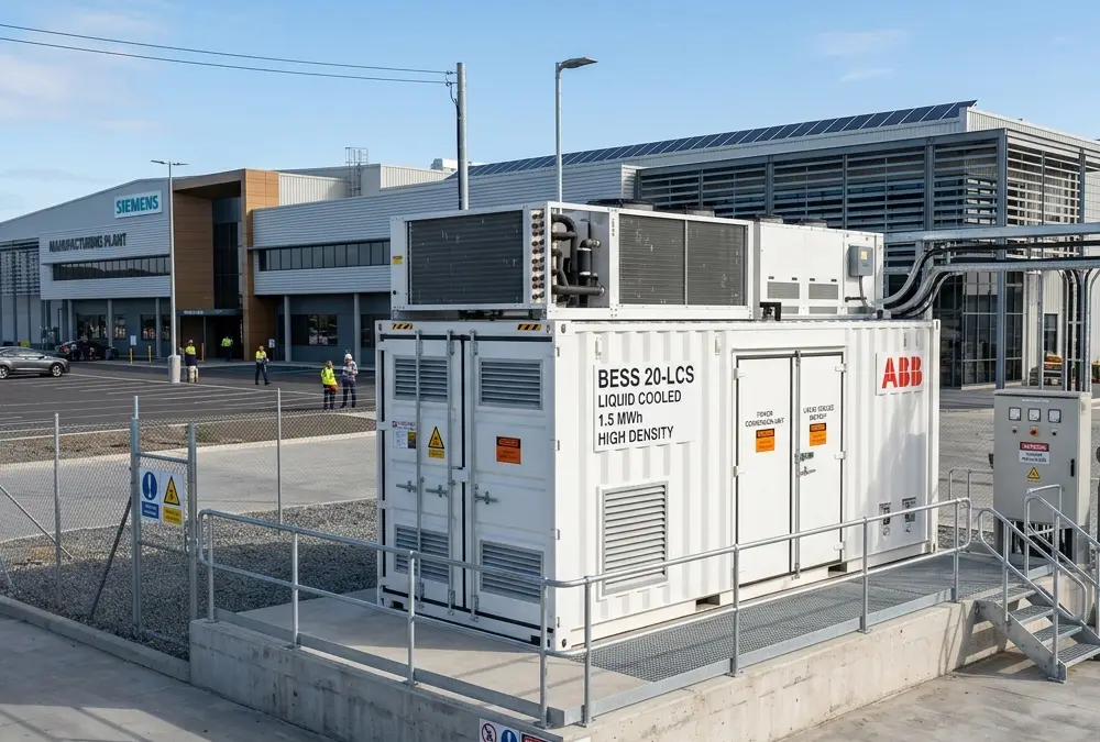
What Is a Liquid Cooling Energy Storage System?
The global transition toward high-power renewable energy infrastructure and ultra-fast fleet electrification demands a shift in how stationary battery systems are thermalized. Deploying a high-capacity liquid cooling battery energy storage system is no longer an optional engineering choice for large enterprises—it is a mandatory foundational requirement for operational safety and economic viability. As grid networks face severe power density strains from high-output factories and logistics hubs, modern operators require advanced, localized safety measures. These setups protect assets against catastrophic thermal hazards while maximizing long-term energy density and daily cycling efficiencies.
Definition of a Liquid Cooled Battery Energy Storage System (BESS)
A liquid cooling battery energy storage system (BESS) is an industrial-grade energy storage solution that utilizes a closed-loop liquid thermal management network instead of ambient air circulation to regulate internal cell temperatures. In high-capacity configurations, managing localized hot spots is a critical priority. Because liquid possesses a significantly higher thermal density than air, a liquid cooling lithium battery storage system can absorb and transfer massive thermal loads generated during rapid charging and discharging phases. This closed-loop configuration maintains battery strings within tight, ideal operating limits, preventing localized cells from experiencing premature capacity fade or uneven internal resistance build-up.
How Liquid Cooling Works in Energy Storage Systems
The operational architecture of a commercial liquid cooled energy storage system relies on continuous conduction. A centralized chiller and pump unit circulates a specialized dielectric or water-glycol coolant fluid through insulated, industrial-grade stainless steel or aluminum pipeline loops. These pipelines connect directly to specialized cooling plates placed in direct physical contact with individual lithium cell casings.
As the cells generate thermal energy during heavy high-current cycling, the heat bypasses the air entirely. It transfers directly through conductive thermal interface materials (TIM) into the circulating fluid. The warmed fluid is pumped rapidly out of the core battery rack modules to an external heat exchanger or condenser coil, cooled back down to its target baseline, and reintroduced into the closed-loop rack layout.
Difference Between Liquid Cooling and Air Cooling Energy Storage Systems
Cooling Efficiency Comparison
Air is a poor thermal conductor. Air-cooled architectures rely on large mechanical fans to blow air across battery modules, which often leads to stagnant air pockets and uneven internal temperatures. Liquid thermal distribution networks deliver a heat transfer coefficient that is up to 25 to 30 times higher than ambient forced air, allowing the system to handle massive thermal spikes effortlessly.
Safety and Thermal Management Differences
If an internal cell fault occurs in an air-cooled enclosure, oxygen circulation from active fans can inadvertently feed localized hot spots, increasing the risk of thermal runaway. Closed-loop liquid setups eliminate external airflow across cell faces and utilize precision-engineered cooling plates to act as localized heat sinks, absorbing thermal energy from a failing cell before it can impact adjacent modules.
Space and Noise Comparison
Air systems require extensive open spacing between battery modules to allow for adequate airflow, which increases the required physical footprint of the project. Conversely, liquid-cooled plates allow cells to be tightly packed together, maximizing volumetric density. Additionally, removing large external air fans dramatically lowers ambient noise levels during heavy cycling operations.
Lifecycle and Maintenance Comparison
Uneven air distribution causes cells in the center of air-cooled racks to degrade much faster than cells on the outside, leading to premature module failure. Liquid circulation provides highly uniform cooling across every single battery module, ensuring consistent, balanced cell aging across the entire installation.
Why More Commercial and Industrial Projects Are Choosing Liquid Cooling Energy Storage Systems
Growing Demand for High-Density Battery Storage
Modern C&I installations face severe physical space limits. Whether expanding an urban manufacturing site or upgrading an executive office park, enterprises need maximum energy storage capacity inside the smallest possible footprint. Utilizing a containerized liquid cooling ESS solution allows developers to pack multiple megawatt-hours of capacity into standard, compact footprint profiles that would require double the real estate if deployed using legacy air-cooled equipment.
Challenges of Traditional Air-Cooled ESS Systems
As industrial workloads transition to high C-rate applications—such as providing high-current buffering for multi-gun ultra-fast EV charging stations—traditional air-cooled systems struggle to maintain safe internal temperatures. When forced-air setups are pushed under heavy duty cycles, they often experience severe temperature differentials across the battery racks, forcing the internal battery management system (BMS) to throttle system output to prevent localized overheating.
Why Liquid Cooling Is Becoming the Mainstream Technology for Modern BESS
Because liquid systems maintain consistent cell-to-cell temperature variations under 2°C to 3°C, they ensure reliable performance during prolonged high-power output windows. This thermal consistency allows commercial operators to confidently run continuous peak shaving, localized load shifting, and high-frequency demand response strategies without encountering thermal-related system shutdowns.
Common Customer Pain Points When Selecting a Liquid Cooling Energy Storage System
Concerns About Battery Safety and Thermal Runaway
Risks of Uneven Battery Temperature
When individual cells within a high-voltage series string operate at different temperatures, they develop unequal internal resistances. Over time, the warmer cells charge faster and discharge deeper than cooler cells, accelerating degradation and increasing the risk of internal short circuits and thermal runaway.
Importance of Multi-Layer Thermal Protection
To protect high-value commercial property, a commercial battery storage system must use layered safety protocols. Modern industrial enclosures combine cell-level mechanical fuses with advanced aerosol fire suppressants, smart outgassing detection sensors, and automated safety overrides that isolate troubled battery racks long before a structural hazard can develop.
Concerns About Long-Term Battery Degradation
How Temperature Affects Battery Lifespan
Lithium cells exposed to sustained operating temperatures above 40°C experience accelerated chemical degradation, causing rapid breakdown of the internal solid electrolyte interphase (SEI) layer. This accelerated aging shortens the system’s useful life, eroding project returns and extending the investment payback period.
Why Consistent Cooling Improves Cycle Life
Maintaining stable, optimal internal temperatures directly protects cell chemistry. Keeping cells consistently between 20°C and 25°C minimizes structural degradation, allowing the battery asset to achieve its full rated cycle life and ensuring predictable, long-term financial performance.
Concerns About Installation, Maintenance, and System Complexity
Liquid Leakage Concerns
Enterprise risk managers often voice concerns about circulating fluid directly adjacent to high-voltage DC electronics. To eliminate this risk, modern systems utilize automotive-grade quick-connect couplings, continuous pressure drop sensors, and multi-point moisture detection alarms to guarantee fluid containment.
System Reliability and Remote Monitoring
Operating complex fluid pumps and chillers requires advanced oversight. Modern commercial storage platforms integrate cloud-connected remote telemetry networks, providing maintenance teams with 24/7 visibility into system pressures, fluid levels, and overall system health.
Importance of Professional EMS + BMS Integration
To achieve maximum operational reliability, the battery management system (BMS) and higher-level energy management system (EMS) must work in perfect synchronization. The BMS monitors cell-level temperatures, while the EMS dynamically adjusts coolant flow rates based on incoming solar generation, building loads, and real-time utility pricing schedules.
Key Advantages of Liquid Cooling Energy Storage Systems
High-Efficiency Heat Dissipation for Battery Storage Systems
Faster Heat Transfer Compared to Air Cooling
Liquid coolants feature a specific heat capacity that is more than four times greater than standard ambient air. This high thermal capacity allows the cooling loops to instantly absorb large thermal surges during rapid charging cycles, keeping high-power operations stable and efficient.
Stable Operation in High-Temperature Environments
During summer peak periods when ambient outdoor temperatures exceed 40°C, traditional air-cooled configurations often struggle to reject heat effectively. Liquid-cooled chillers handle these extreme ambient conditions easily, maintaining safe, stable internal temperatures to ensure uninterrupted factory performance.
Uniform Battery Temperature Distribution
Reducing Cell Temperature Difference
Advanced liquid distribution configurations ensure that the temperature delta between the absolute warmest and coolest cells across the entire system remains under 2°C, delivering uniform thermal balance throughout the installation.
Improving Battery Consistency and Performance
Eliminating internal thermal variations ensures that all cells across the high-voltage series string age at an identical rate, preserving system balancing and unlocking maximum discharge performance from the battery bank.
Improved Safety for Commercial and Industrial BESS
Lower Thermal Runaway Risk
Because liquid cooling plates provide direct, non-stop heat dissipation at the cell level, any localized heat surge from an internal cell fault is rapidly absorbed and carried away, preventing the heat from spreading to adjacent cells.
Better Fire Prevention Performance
Sealed, liquid-cooled enclosures eliminate continuous external air ventilation across cell faces, creating a controlled internal environment that isolates the battery modules and optimizes the effectiveness of automated fire suppression systems.
Enhanced Battery Protection Through BMS Coordination
If internal temperatures climb during unexpected operational overloads, the integrated BMS communicates instantly with the cooling loops to increase pump speeds and chiller output, providing proactive safety protection before structural limits are reached.
Compact Footprint and Higher Energy Density
Space Optimization for Commercial Facilities
Eliminating the large internal air ventilation gaps required by legacy forced-air systems allows design teams to minimize the footprint of the enclosure, saving valuable commercial land or floor space.
Higher Capacity in Containerized ESS Projects
Modern containerized liquid cooling ESS solution designs allow engineers to pack up to 3.4MWh to 5MWh of storage capacity into a standard 20-foot shipping container envelope, delivering nearly double the energy density of older air-cooled designs.
Low Noise Operation in Urban and Commercial Applications
Quiet Operation for Hotels, Offices, and Residential Areas
Large mechanical air fans generate considerable ambient noise, which can conflict with local zoning laws in commercial areas. Liquid cooling networks run on highly quiet internal circulation pumps, making them an excellent choice for hotels, corporate office parks, and urban environments.
Reduced Dependence on Large Air Cooling Fans
By utilizing liquid-glycol loops for primary thermal management, the system minimizes the need for loud, high-volume external air blowers, keeping overall noise profiles low during nighttime operation.
Strong Compatibility with Modern Energy Systems
Integration with Solar + Storage Systems
Pairing a high-density liquid-cooled enclosure with an onsite solar array allows businesses to safely store large surges of daytime solar energy and dispatch it smoothly during high-tariff evening windows.
Compatibility with EV Charging Infrastructure
Deploying a liquid cooled BESS for EV charging stations provides an essential high-power buffer for commercial charging hubs. The system absorbs the heavy, sudden power spikes from fast-charging vehicles, protecting the local grid from destabilizing voltage drops.
Smart EMS Integration for Peak Shaving and Load Management
Advanced EMS controls monitor building loads in real time, automatically discharging the battery bank during high-demand periods to keep total grid draw flat and eliminate expensive utility peak demand penalties.
Liquid Cooling Energy Storage System Components Explained
An industrial-grade liquid-cooled storage installation integrates five core structural sub-systems:
Lithium Battery System and Battery Modules
LFP Battery Technology in Liquid Cooled ESS
Modern commercial storage systems rely almost exclusively on Lithium Iron Phosphate (LiFePO4 or LFP) cell chemistry. LFP features a robust crystalline structure that delivers superior safety, exceptional thermal stability, and a significantly longer cycle life compared to weight-optimized electric vehicle chemistries like NMC.
Battery Rack Design and Modular Architecture
Individual LFP cells are laser-welded into modular battery packs equipped with integrated internal cooling plates, high-current busbars, and localized monitoring links. These packs are arranged vertically in heavy-duty structural steel racks to achieve the high-voltage DC requirements of commercial PCS inverters.
Liquid Cooling Thermal Management System
Coolant Circulation System
Includes multi-stage industrial pumps, expansion tanks, and highly insulated stainless steel or reinforced polymer piping designed to ensure continuous, reliable fluid flow across all battery modules.
Heat Exchangers and Cooling Plates
Precision-engineered aluminum alloy plates built with internal fluid channels are placed in direct contact with the cells. These plates interface with a primary heat exchanger to ensure rapid, efficient heat transfer away from the battery modules.
Intelligent Temperature Control Strategies
The cooling loop uses smart variable-frequency drives on the pumps and chillers, automatically adjusting fluid flow speeds and cooling output based on real-time cell parameters to minimize internal parasitic power consumption.
Battery Management System (BMS)
Real-Time Cell Monitoring
The BMS tracks cell-level metrics, including individual cell voltages, continuous current flows, internal resistance metrics, and localized surface temperatures across every battery rack module.
Thermal Protection and Fault Detection
If an individual cell shows a sudden temperature variation, the BMS detects the anomaly instantly, isolates the affected rack section via automated DC contactors, and alerts the operator before a broader electrical issue can develop.
Power Conversion System (PCS)
Bidirectional Power Conversion
The PCS is a highly efficient, bidirectional power inverter. It converts incoming grid AC power into stable DC power to charge the battery banks and transforms stored DC power back into grid-synchronized three-phase AC power to run facility equipment.
Grid Connection and Energy Dispatch
Equipped with high-speed digital signal processors, the PCS syncs seamlessly with local utility lines, responding within milliseconds to EMS dispatch commands to manage active and reactive power needs.
Energy Management System (EMS)
Smart Energy Scheduling
The EMS serves as the higher-level software brain of the installation, executing complex operational strategies to optimize financial returns based on building demand patterns and dynamic utility rates.
Peak Shaving and Demand Response Optimization
The EMS continuously tracks facility energy draw. When consumption approaches expensive utility thresholds, it triggers the battery bank to discharge, keeping the grid draw flat and capturing valuable savings.
Fire Protection and Safety Systems
Fire Suppression Technologies
The enclosure is equipped with automated multi-stage fire safety networks, combining sensitive smoke, gas, and temperature sensors with localized clean-agent gas or aerosol fire suppression systems.
Multi-Level Safety Architecture
Features layered physical and digital protection mechanisms—ranging from cell-level pressure release vents to main circuit breakers and structural explosion venting panels—ensuring total property safety.
Technical Performance Benchmarks (2025–2026 Data)
To help financial and engineering teams evaluate technology options, the table below outlines key technical performance differences between standard air-cooled and modern liquid-cooled storage architectures based on current 2026 industry benchmarks:
| Performance & Operational Parameter | Standard Air-Cooling ESS Architecture | Modern Liquid-Cooling ESS Solution | Verified Industry Source / Report |
|---|---|---|---|
| System Volumetric Energy Density | Baseline (Requires significant open airflow gaps) | +35% to +45% higher capacity per sq. meter | BloombergNEF Report |
| Cell-to-Cell Temperature Delta | 5°C to 8°C (Higher risk of uneven cell aging) | ≤ 2.0°C to 2.5°C (Excellent uniformity) | Lazard’s Cost of Storage Study |
| System Round-Trip Efficiency (RTE) | 85.5% – 87.5% (High auxiliary fan losses) | 89.5% – 92.0% (Low conversion losses) | Standard Manufacturer Specs |
| Average Battery Degradation Rate | Baseline Capacity Loss | 20% longer operational life cycle | IEA Technology Report |
| Enclosure Ambient Noise Profile | 75 dB – 82 dB at 1 meter (Loud external fans) | ≤ 60 dB – 65 dB at 1 meter (Highly quiet) | Civil Acoustic Codes |
Technical Deep-Dive: Sizing and Efficiency Calculations
To accurately measure the performance of an industrial energy storage solution, engineering teams review verified operational calculations:
By keeping internal cell temperatures stable and reducing the run time of large, energy-intensive cooling fans, liquid-cooled architectures lower internal parasitic power consumption, raising the system’s overall round-trip efficiency (RTE).
Parasitic Load Evaluation
The total power required to run a storage installation includes both the energy stored in the cells and the auxiliary power consumed by the thermal management system:
Because liquid cooling systems transfer heat with exceptional efficiency, the chiller loop can remain in a low-power standby mode during low-load periods, reducing auxiliary power drain and maximizing long-term project ROI.
Applications of Liquid Cooling Energy Storage Systems
Utility-Scale Battery Energy Storage Power Stations
Large utility grids deploy high-capacity liquid-cooled configurations to provide critical grid stabilization services, including rapid frequency regulation and spinning reserves to balance intermittent renewable energy generation.
Wind Farms and Solar Power Plants
Renewable energy developers couple large generation arrays with advanced storage solutions to store excess daytime or high-wind energy, reducing curtailment losses and ensuring clean power can be dispatched during high-tariff periods.
Liquid Cooling ESS for Data Centers
Modern data centers running intensive AI and cloud computing workloads require non-stop, reliable power infrastructure. High-density liquid-cooled battery installations provide space-efficient, instantaneous backup power to shield critical servers against unexpected utility outages.
Commercial and Industrial Peak Shaving Applications
Manufacturing plants, cold storage warehouses, and large commercial buildings utilize intelligent storage systems to smooth out erratic energy profiles, lowering monthly demand charges and cutting overall factory electricity bills.
Demand Response and Smart Grid Applications
Enterprises use smart energy storage assets to participate in utility demand response programs, earning reliable revenue by reducing grid draw on short notice to support regional grid stability.
Backup Power and Emergency Energy Storage Systems
Critical public infrastructure—including hospitals, emergency response hubs, and telecommunications networks—uses reliable liquid-cooled storage setups to replace loud, high-emission diesel generators with a silent, zero-carbon backup alternative.
Transportation, Installation, and Maintenance of Liquid Cooling Energy Storage Systems
Transportation Requirements for Liquid Cooled ESS
Industrial storage configurations are engineered inside standard, high-strength ISO shipping containers, allowing them to be transported safely via standard marine, rail, and flatbed truck networks. Equipment arrives factory-sealed and pre-tested to streamline on-site deployment.
Installation Requirements for Liquid Cooling Battery Storage Systems
Outdoor concrete foundation pads must be level, properly engineered to handle heavy weight loads, and positioned away from standing water risks. All high-voltage DC conduit runs and external fluid plumbing lines must follow strict local engineering codes.
Operation and Maintenance of Liquid Cooling ESS
Preventative maintenance schedules are simple but essential. Teams perform annual coolant quality checks, inspect pipeline fittings for proper sealing, clear external condenser coils, and review automated EMS software performance logs.
Liquid Cooling vs. Air Cooling Energy Storage Systems
While legacy air-cooled enclosures offer lower initial equipment costs, they introduce significant long-term operational trade-offs. Air-cooled infrastructure requires a larger installation footprint, runs with higher ambient noise profiles, and can lead to uneven cell degradation due to internal temperature variations.
Investing in a premium, liquid-cooled configuration delivers higher volumetric energy density, superior thermal uniformity, and a longer overall system lifecycle. The significant reduction in internal parasitic fan power combined with extended cell longevity delivers a lower Total Cost of Ownership (TCO), ensuring superior financial performance over the lifespan of your commercial asset.
Technical Description of Storage Alternative Technologies
When exploring options for an industrial project, it is helpful to clarify alternative energy storage concepts to see why liquid-cooled lithium networks remain the commercial benchmark:
- Flow Batteries (e.g., Vanadium Redox Flow Systems): These systems store energy in external liquid electrolyte tanks. They offer exceptional lifespan with virtually no capacity degradation over decades, making them a strong fit for large, multi-megawatt, long-duration utility projects. However, they suffer from a lower round-trip efficiency (65%–75%) and require a much larger physical footprint, making them impractical for space-constrained industrial sites.
- Sodium-Ion Batteries: An emerging alternative technology that replaces lithium with abundant sodium. They offer excellent low-temperature performance and strong safety characteristics. However, they carry a lower volumetric energy density and are in the early stages of industrial commercialization, leaving them without the long-term field-testing data that backs LFP technology.
- Lead-Acid Batteries (Legacy Systems): While cheap upfront, lead-acid systems are entirely obsolete for modern high-power C&I applications. They suffer from a very short cycle life (500–1,500 cycles), heavy environmental toxicity constraints, low efficiency profiles, and limited depth of discharge capabilities (50%).
💡 Community Insight & DIY Feasibility
Some facility managers note discussions on industrial forums asking: “Can a business source individual lithium cells online and assemble their own 100kWh battery bank to save on equipment costs?” From an industrial engineering perspective, the answer is a definitive no. Assembling raw lithium cells into a multi-kilowatt configuration requires professional cleanroom manufacturing, automated laser-welding equipment, precise thermal management integration, and complex high-voltage safety engineering. A self-assembled DIY system cannot secure official CE or IEC 62619 compliance certifications, will fail local grid interconnection reviews, and carries significant safety hazards that violate commercial property insurance policies. Commercial reliability requires field-proven, factory-certified hardware.
Why Choose AnengJi Liquid Cooling Energy Storage Systems?
AnengJi delivers high-performance, precision-engineered energy storage infrastructure tailored specifically to the demanding operational needs of the modern C&I sector.
Advanced Liquid Cooling Thermal Management Technology
AnengJi systems utilize advanced, closed-loop liquid thermal management networks designed to keep internal cell temperature deltas under 2°C, maximizing system efficiency and protecting your asset against accelerated capacity loss.
Integrated BMS + PCS + EMS Architecture
Our configurations feature a fully unified system architecture where the cell-level BMS, high-efficiency bidirectional PCS, and smart cloud-connected EMS are engineered to work together perfectly, eliminating communication errors and optimizing energy dispatch.
High-Efficiency LFP Battery Systems
Our structures rely exclusively on premium, certified Lithium Iron Phosphate cell chemistry, delivering exceptional thermal stability, robust fire safety performance, and long cycle lifecycles under heavy industrial workloads.
CE, IEC, and UL9540A Certified Products
Safety is central to our engineering philosophy. AnengJi commercial storage products carry full international certifications—including CE, IEC 62619, and full UL9540A thermal runaway safety compliance—ensuring simple permitting approvals and smooth integration with local utility lines.
Extensive Commercial and Utility-Scale Project Experience
With a deep portfolio of successful energy storage deployments worldwide, AnengJi brings valuable technical design and site execution experience to your commercial project, ensuring maximum long-term performance.
Overseas Technical Support and Spare Parts Services
We protect your operational uptime through our responsive international service infrastructure. Sourcing from our localized technical centers and fully stocked spare parts hubs ensures your facility receives rapid support and dependable service whenever needed.
Conclusion: Why Liquid Cooling Is the Future of Battery Energy Storage Systems
Transitioning to high-power energy workloads requires highly efficient, smart thermal management systems. Utilizing an advanced liquid cooling battery energy storage system allows commercial and industrial facilities to overcome the physical footprint and safety limitations of older air-cooled designs. Keeping internal cell temperatures completely uniform allows liquid-cooled configurations to maximize system safety, deliver higher energy density, and extend the operational lifespan of your battery asset. Partnering with an experienced infrastructure manufacturer like AnengJi ensures your business receives a safe, efficiently engineered storage solution built to lower utility costs and provide reliable power for decades to come.
Quick Summary of Liquid Cooling Energy Storage Systems
| Question | Quick Answer |
|---|---|
| What is a liquid cooling energy storage system? | A high-efficiency battery energy storage system (BESS) that utilizes a closed-loop liquid glycol coolant network to maintain optimal, safe internal cell temperatures. |
| Why is liquid cooling better than air cooling? | It delivers significantly faster heat dissipation, maintains precise cell temperature uniformity, enables higher energy density, runs quietly, and extends overall battery lifecycles. |
| Where are liquid cooling ESS systems used? | Ideal for utility-scale power stations, high-output industrial factories, data centers, solar generation plants, and commercial EV charging station locations. |
| Does liquid cooling improve battery lifespan? | Yes. Keeping cell-to-cell temperature variations under 2°C minimizes internal cell stress, preventing uneven degradation and extending the system’s useful life. |
| Is liquid cooling ESS suitable for commercial projects? | Yes, it is highly recommended for high-capacity C&I applications where minimizing installation space and maximizing long-term ROI are core priorities. |
FAQ About Liquid Cooling Energy Storage Systems
What is the difference between liquid cooling and air cooling ESS?
Air-cooled systems rely on motorized fans to circulate ambient air across battery packs, which can create internal hot spots and requires significant space between modules. Liquid-cooled configurations use a closed-loop fluid pipeline connected directly to internal cooling plates, delivering vastly superior heat dissipation and higher energy density within a compact footprint.
Is liquid cooling safer for lithium battery storage systems?
Yes, liquid cooling provides significantly higher structural safety. The conductive cooling plates rapidly absorb and carry away excess thermal energy from individual cells, preventing localized heat from spreading to adjacent modules and effectively minimizing thermal runaway risks.
How long does a liquid cooled battery storage system last?
When managed by an advanced BMS and liquid cooling network that maintains stable operating temperatures between 20°C and 25°C, high-quality LFP cells can deliver 6,000 to 8,000 complete operational cycles, translating to a service life of 15 to 20 years.
What coolant is used in liquid cooling ESS systems?
Most industrial installations utilize a specialized, inhibited water-glycol mixture (similar to automotive coolant) or an advanced dielectric fluid. These fluids are chosen because they offer excellent thermal conductivity, provide dependable freeze protection, and prevent internal system corrosion.
Are liquid cooling energy storage systems expensive?
While liquid-cooled configurations carry a slightly higher initial hardware cost compared to legacy air-cooled boxes, they deliver a lower Total Cost of Ownership (TCO). The gain in system round-trip efficiency combined with a 20% longer operational life delivers significantly higher long-term financial returns.
Can liquid cooled ESS systems support EV fast charging stations?
Yes, absolutely. A liquid cooled BESS for EV charging stations serves as an ideal high-power buffer. It safely handles the rapid, intense thermal surges generated during fast fleet charging sessions, allowing properties to offer ultra-fast charging without requiring costly grid transformer upgrades.
 https://anengjipower.com/wp-content/uploads/2026/10/AnengjiPowr-AC-Coupled-Battery-Storage-at-a-CI-Solar-Site.webp
675
1000
Charging Station Engineer
https://anengjipower.com/wp-content/uploads/2025/09/anengji-dc-fast-charging-station-manufacturer-and-supplier-logo-white-1.png
Charging Station Engineer2026-10-16 03:03:192026-10-16 03:03:49What Is AC-Coupled Battery Storage? C&I BESS Guide
https://anengjipower.com/wp-content/uploads/2026/10/AnengjiPowr-AC-Coupled-Battery-Storage-at-a-CI-Solar-Site.webp
675
1000
Charging Station Engineer
https://anengjipower.com/wp-content/uploads/2025/09/anengji-dc-fast-charging-station-manufacturer-and-supplier-logo-white-1.png
Charging Station Engineer2026-10-16 03:03:192026-10-16 03:03:49What Is AC-Coupled Battery Storage? C&I BESS Guide https://anengjipower.com/wp-content/uploads/2026/10/AnengjiPower-What-Is-Peak-Shaving-at-an-Industrial-Site.webp
675
1000
Charging Station Engineer
https://anengjipower.com/wp-content/uploads/2025/09/anengji-dc-fast-charging-station-manufacturer-and-supplier-logo-white-1.png
Charging Station Engineer2026-10-15 06:49:012026-10-15 06:50:23What Is Peak Shaving? How Battery Energy Storage Reduces C&I Peaks
https://anengjipower.com/wp-content/uploads/2026/10/AnengjiPower-What-Is-Peak-Shaving-at-an-Industrial-Site.webp
675
1000
Charging Station Engineer
https://anengjipower.com/wp-content/uploads/2025/09/anengji-dc-fast-charging-station-manufacturer-and-supplier-logo-white-1.png
Charging Station Engineer2026-10-15 06:49:012026-10-15 06:50:23What Is Peak Shaving? How Battery Energy Storage Reduces C&I Peaks https://anengjipower.com/wp-content/uploads/2026/10/anengjipower-Peak-Shaving-vs-Load-Shifting-at-an-Industrial-Site.webp
675
1000
Charging Station Engineer
https://anengjipower.com/wp-content/uploads/2025/09/anengji-dc-fast-charging-station-manufacturer-and-supplier-logo-white-1.png
Charging Station Engineer2026-10-14 07:47:372026-10-14 07:48:01Peak Shaving vs Load Shifting: C&I Energy Storage Decision Guide
https://anengjipower.com/wp-content/uploads/2026/10/anengjipower-Peak-Shaving-vs-Load-Shifting-at-an-Industrial-Site.webp
675
1000
Charging Station Engineer
https://anengjipower.com/wp-content/uploads/2025/09/anengji-dc-fast-charging-station-manufacturer-and-supplier-logo-white-1.png
Charging Station Engineer2026-10-14 07:47:372026-10-14 07:48:01Peak Shaving vs Load Shifting: C&I Energy Storage Decision Guide


Leave a Reply
Want to join the discussion?Feel free to contribute!